
Water sprays for dust control on mining machines

a technology of dust control and water spray, which is applied in the field of mining, can solve the problems of significant interaction between sprays, roll-back on the miner chassis toward, and increase the droplet size after interaction, so as to improve the spray efficiency, improve the effect of dust suppression, and simplify the concentration of dus

Inactive Publication Date: 2014-01-21
SOUTHERN ILLINOIS UNIVERSITY
View PDF8 Cites 6 Cited by
  • Summary
  • Abstract
  • Description
  • Claims
  • Application Information

AI Technical Summary

Benefits of technology

The patent text describes a method to improve the efficiency of sprays used to suppress dust in continuous mining operations. The invention uses different types of sprays and configures them appropriately to minimize the impact of dust on the mining process. The technical effect of this invention is to effectively control dust in the mining area, reducing airborne dust concentrations and improving spray efficiency.

Problems solved by technology

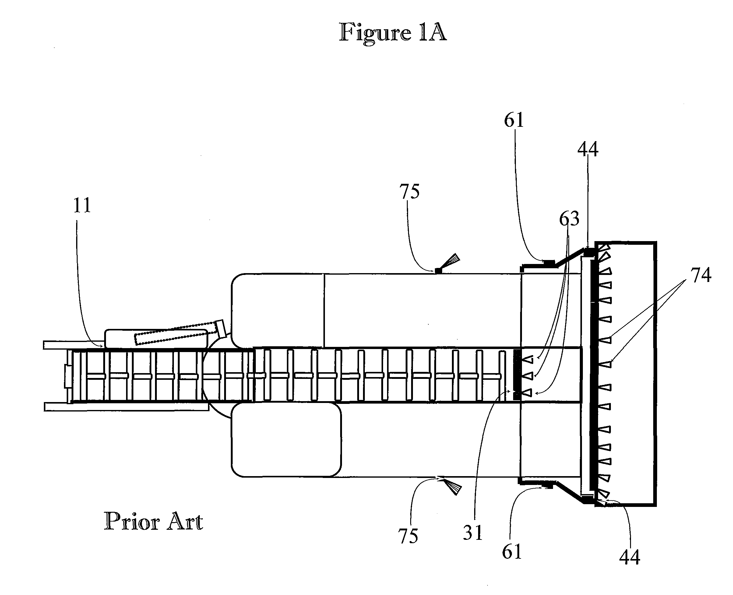
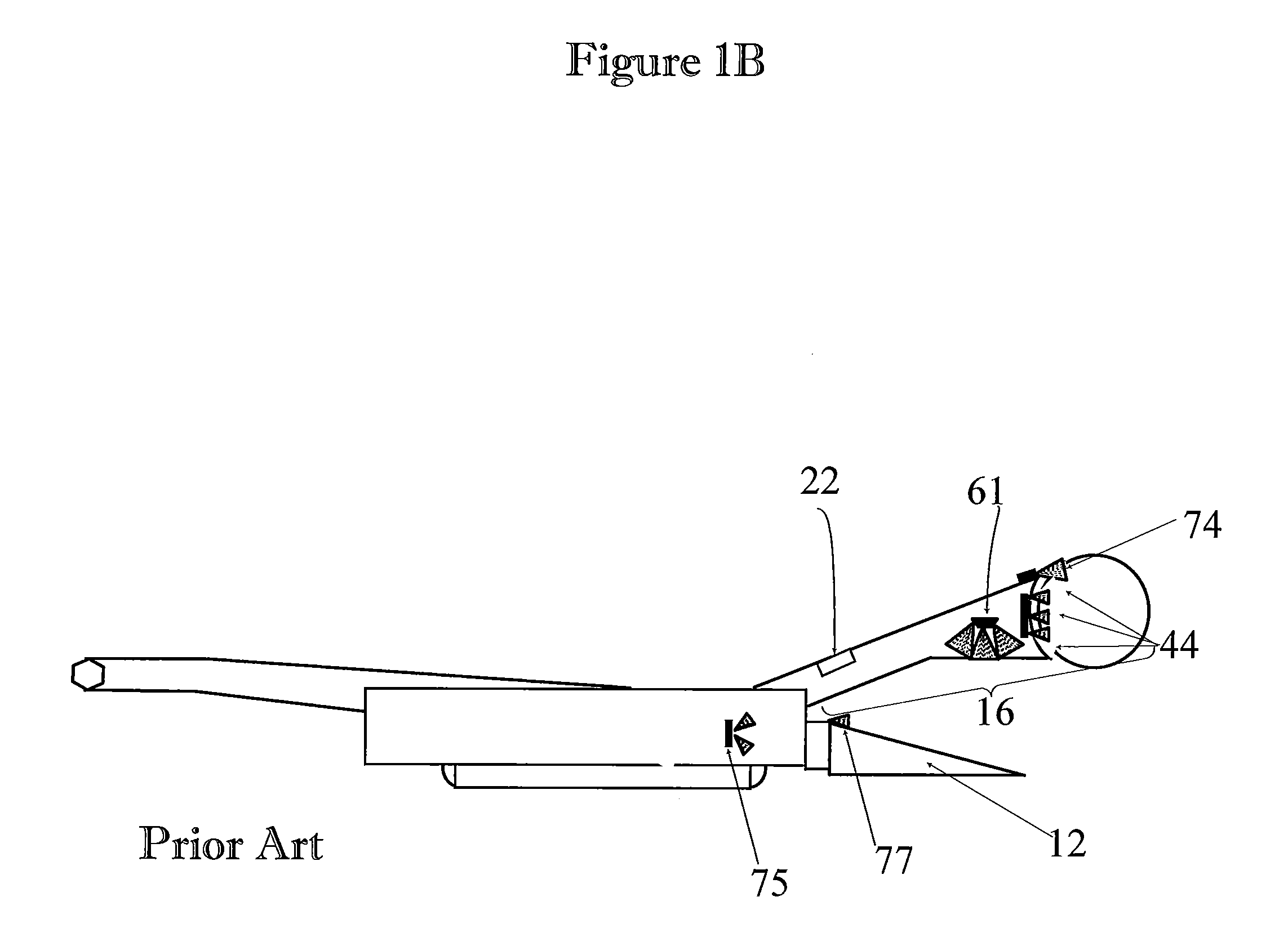
Location of boom sprays for the cutter drum, loading pan sprays, under-boom spray pressure, type of sprays used and high water spray pressure (˜100 psi) used can displace dust-laden air along the roof level, towards the sides, and back of the miner and results in roll-back on the miner chassis toward the miner operator and batch haulage unit operator.
Spatial location of sprays on the spray blocks and type of sprays used can typically result in significant interaction among sprays.
These interactions (caused by different sprays colliding with each other) can result in droplet size increase after interaction.
In several cases, these sprays intercept each other upon discharge from the orifice resulting in not only larger droplets that negatively impact dust control, but also in wasted energy.
Since the ability to capture dust requires that the water droplet size be near the size of the dust particle, this interaction significantly reduces the potential to wet the finer fractions of dust.
However, the seals are generally incomplete due to the large distance between the sprays and the excavation sides and interactions between these side sprays and the boom and under-boom sprays.

Method used


Image

  • Water sprays for dust control on mining machines
  • Water sprays for dust control on mining machines
  • Water sprays for dust control on mining machines

Examples


Embodiment Construction

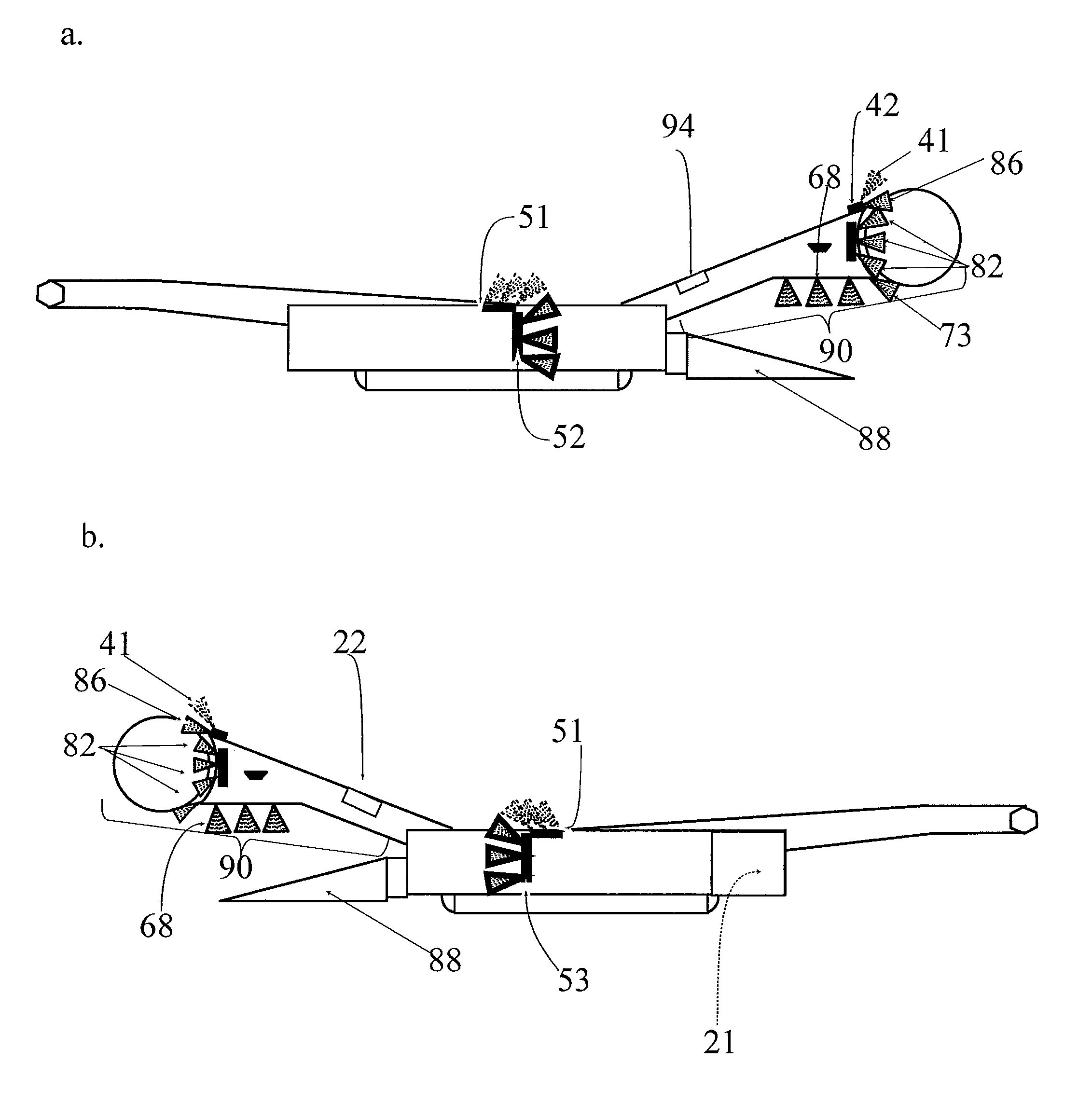
[0064]The primary means of dust control should be preventing the dust generated at the cutting faces from becoming airborne. Hollow-cone or flat sprays directed into the bits and the cutting face should help achieve this objective and cool the cutting bits.

[0065]Once the dust is airborne, the flooded-bed scrubber is an efficient mechanism at the face to capture the dust and wet it within the scrubber. Hence, the goal should be to maximize the amount of airborne dust that gets directed into the scrubber. To accomplish this, appropriately angled flat sprays or wide-angle hollow-cone sprays on the boom behind the first set of sprays create a shroud containing the generated dust near the face area in a restricted volume.

[0066]Similarly, flat or hollow-cone sprays underneath the cutting boom may envelope the gap between the pan and the boom and contain the airborne dust such that the central suction port of the scrubber is able to draw it inside the scrubber. Some miners have under-boom ...


PUM


Abstract

This invention refers to innovative water sprays applications to significantly improve coal and quartz dust control around a continuous miner. Significant dust control is achieved through utilizing different types of sprays at locations on the top and sides of the miner chassis to create water curtains or shrouds of water around zones of high dust concentration and zones of high concentration dust transport. This is called “multiple lines of defense” spray system (MLD.) This invention also provides a method of reducing dust around a continuous miner by configuring a spray system, located at the top or sides of the cutter boom, thereby improving control of respirable dust.

Description

CROSS-REFERENCE TO RELATED APPLICATIONS[0001]This application claims priority to an earlier filed co-pending Provisional Patent application No. 61 / 366,356 filed Jul. 21, 2010 entitled Innovative Water Sprays Applications for Dust Control on Mining Machines.FIELD OF THE INVENTION[0002]This invention relates to mining. More specifically, it relates to dust control around a continuous miner or similar mining machine through the use of water spray applications.BACKGROUND OF THE INVENTION[0003]Increased productivity and high out-of-coal seam dilution (25% to 30%) in the US and around the globe continue to generate dust control problems in mining areas. After a significant decrease in the number of incidents of coal worker's pneumoconiosis (CWP) over the last several decades, the number of reported cases in this decade is increasing. The primary cause of CWP is inhalation of respirable dust in a confined workplace; specifically, the inhalation of coal and quartz dust in a mine. The Nation...

Claims


Application Information

Patent Timeline
Patent Type & Authority Patents(United States)
IPC IPC(8): E21C35/22
CPCE21C27/24E21C35/22E21C35/23
Inventor CHUGH, YOGINDER, P.
Owner SOUTHERN ILLINOIS UNIVERSITY
Learn More