
Production equipment and production method for precipitation hardened alloy strip

a production equipment and alloy strip technology, applied in lighting and heating apparatus, furnaces, heat treatment equipment, etc., can solve the problems of insufficient quenching, warping or twisting of alloy strips, difficult to uniformly spray cooling water jets, etc., to achieve uniform cooling, improve surface condition, and improve shape

Active Publication Date: 2014-01-28
NGK INSULATORS LTD
View PDF14 Cites 0 Cited by
  • Summary
  • Abstract
  • Description
  • Claims
  • Application Information

AI Technical Summary

Benefits of technology

[0007]The production equipment disclosed in Patent Document 1 cools down only one face, the surface or the rear face, of the alloy strip each time and may cause insufficient quenching. The difference of the cooling timing between the surface and the rear face may result in uneven cooling of the alloy strip in the strip thickness direction and cause the warping or the twisting of the alloy strip. The production equipment disclosed in Patent Document 2, on the other hand, utilizes the pressure difference to prevent penetration of the water vapor into the furnace. There would be, however, a further demand for more effectively preventing penetration of the water vapor and giving an alloy strip having a better surface condition. It is not easy to uniformly spray the jets of cooling water onto the alloy strip from the spray nozzles. There would thus be a further demand for attaining the more uniform cooling and giving an alloy strip having a better shape.
[0008]By taking into account the issue discussed above, an object of the present invention is to provide production equipment and a production method for precipitation hardened alloy strip, which is structured to quench an alloy strip and give a precipitation hardened alloy strip having a good shape and a favorable surface condition.
[0009]The inventors have intensively studied to attain at least part of the object mentioned above and the other relevant requirements and have completed the present invention based on the finding that a pair of cooling rolls adopted to hold an alloy strip therebetween effectively quenches the alloy strip and gives a precipitation hardened alloy strip having a good shape and a favorable surface condition.
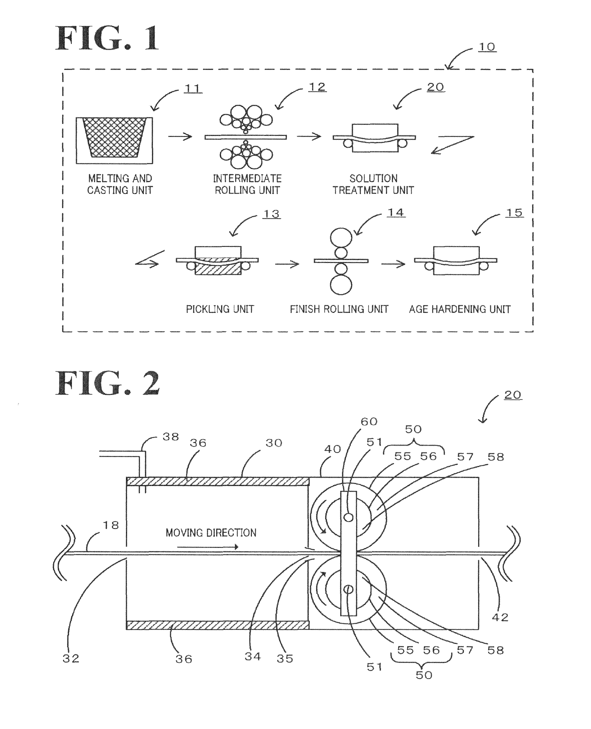
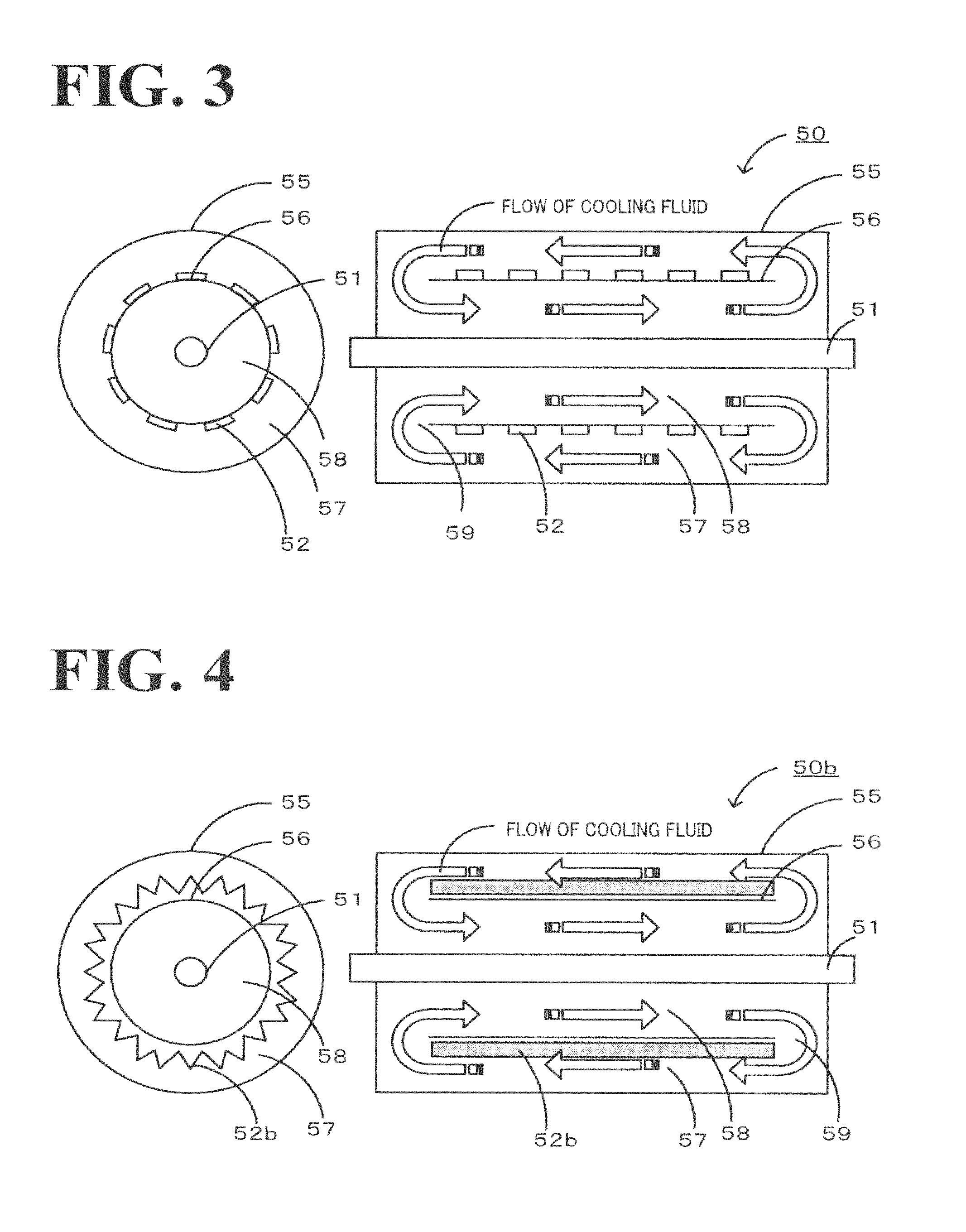
[0011]The production equipment for the precipitation hardened alloy strip according to this aspect of the invention uses the pair of cooling rolls to simultaneously cool down the alloy strip on both faces. This arrangement assures the high cooling efficiency and thereby enables the alloy strip to be quenched. Compared with using one single roll, using the pair of cooling rolls allows for reduction of the heat capacity and the diameter of each cooling roll and thereby shortens the distance and the time interval until the start of cooling the heated alloy strip, thus enhancing the temperature decrease rate. This cooling mechanism adopted in the invention has a lower potential for generation of the water vapor, compared with a cooling mechanism of spraying the flow of cooling water. There is accordingly no need for setting a wide distance between the heating chamber and the cooling device, for the purpose of preventing penetration of the water vapor into the heating chamber. The narrower distance assures the higher temperature decrease rate. As the alloy strip is in contact with the cooling rolls, linear contact areas of the alloy strip are cooled down simultaneously on the surface and the rear face by the pair of cooling rolls. This lowers the potential of uneven cooling and gives a precipitation hardened alloy strip having a good shape. The application of the cooling rolls for cooling does not require any equipment as the source of water vapor in the cooling chamber and allows for restriction of water vapor-induced oxide coating, thus giving a precipitation hardened alloy strip having a favorable surface condition.

Problems solved by technology

The production equipment disclosed in Patent Document 1 cools down only one face, the surface or the rear face, of the alloy strip each time and may cause insufficient quenching.
The difference of the cooling timing between the surface and the rear face may result in uneven cooling of the alloy strip in the strip thickness direction and cause the warping or the twisting of the alloy strip.
It is not easy to uniformly spray the jets of cooling water onto the alloy strip from the spray nozzles.

Method used


Image

  • Production equipment and production method for precipitation hardened alloy strip
  • Production equipment and production method for precipitation hardened alloy strip
  • Production equipment and production method for precipitation hardened alloy strip

Examples


example 1

[0054]A Cu—Be—Co alloy having a Cu-based composition Containing 1.90% by mass of Be and 0.20% by mass of Co was molten, cast, and cold rolled to prepare material alloy strip of 50 mm in width and 0.27 mm in thickness. The composition of the alloy was determined by the previous chemical analysis, and the thickness was measured with a micrometer. The prepared material alloy strip was subjected to continuous solution treatment as explained below. The material alloy strip was heated to 800° C. in a heating chamber kept under a pressure of 0.15 MPa in a nitrogen atmosphere. This temperature was indicated by a thermocouple located in the neighborhood of a terminal end of the heating chamber. The heated material alloy strip was continuously introduced through a transport opening into a connecting cooling chamber and was cooled down by a pair of cooling rolls located in the cooling chamber. Each of the cooling rolls was made of stainless steel (SUS316) and had a dual structure of an outer c...

examples 2 to 7

[0055]An alloy strip of Example 2 was obtained according to the same procedure as that of Example 1, except that each of cooling rolls adopted had a dual structure of an outer cylinder having a diameter of 60 mm and a thickness of 5 mm and an inner cylinder having a diameter of 30 mm and a thickness of 5 mm. An alloy strip of Example 3 was obtained according to the same procedure as that of Example 1, except that the thickness of the material alloy strip was 0.10 mm and that each of cooling rolls adopted had a dual structure of an outer cylinder having a diameter of 200 mm and a thickness of 9 mm and an inner cylinder having a diameter of 140 mm and a thickness of 9 mm. An alloy strip of Example 4 was obtained according to the same procedure as that of Example 1, except that the surface of each of cooling rolls was plated with a hard Cr layer having a film thickness of 97 μm. An alloy strip of Example 5 was obtained according to the same procedure as that of Example 1, except that t...

example 8 and 9

[0056]An alloy strip of Example 8 was obtained according to the same procedure as that of Example 1, except that a Cu—Ni—Si alloy having a Cu-based composition containing 2.40% by mass of Ni and 0.60% by mass of Si was used, that the thickness of the material alloy strip was 0.15 mm, and that the heating temperature was 850° C. An alloy strip of Example 9 was obtained according to the same procedure as that of Example 8, except that the heating temperature was 700° C.


PUM

PropertyMeasurementUnit
temperatureaaaaaaaaaa
pressureaaaaaaaaaa
pressureaaaaaaaaaa

Abstract

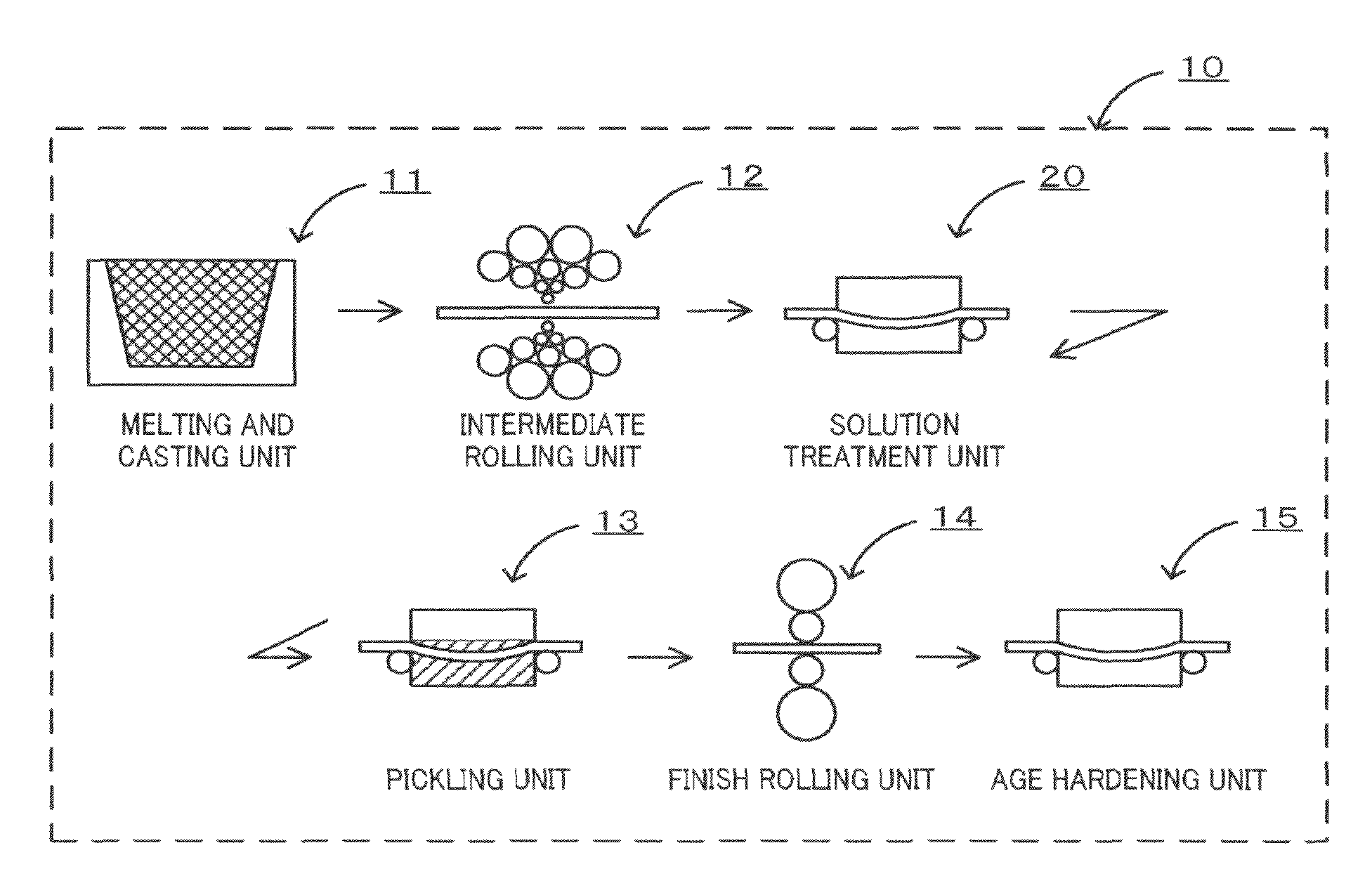
In the production equipment for a precipitation hardened alloy strip, a solution treatment unit includes a heating chamber provided to heat the material alloy strip having a precipitation hardening alloy composition to a temperature of not lower than a recrystallization temperature but not higher than a melting point, a cooling chamber located adjacent to the heating chamber, and a pair of cooling rolls incorporated in the cooling chamber to hold therebetween and cool down the material alloy strip heated in the heating chamber. This production equipment can quench the material alloy strip to form a solid solution supersaturated with precipitation hardening elements and thereby forming a precipitation hardened alloy strip having a good shape and a favorable surface condition.

Description

BACKGROUND OF THE INVENTION[0001]1. Field of the Invention[0002]The present invention relates to production equipment and a production method for precipitation hardened alloy strip.[0003]2. Description of the Related Art[0004]One proposed structure of production equipment for alloy strip has temperature-controlling single rolls arranged in zigzag to be in contact with heated alloy strip and alternately quench one face, the surface or the rear face of the heated alloy strip (see, for example, Patent Document 1). The production equipment disclosed in Patent Document 1 is supposed to have a high energy efficiency for cooling and save both the power consumption and the installation space. Another proposed structure of production equipment has a cooling chamber located on a heat treatment metal material discharge side of an annealing furnace. Spray nozzles are provided in the cooling chamber to cool down the metal material. The pressure of an atmospheric gas in the annealing furnace is m...

Claims


Application Information

Patent Timeline
Patent Type & Authority Patents(United States)
IPC IPC(8): C21D9/573
CPCC22F1/047C22F1/002C22C1/00C22F1/08C21D9/573F27B9/28C21D9/5737C21D1/44
Inventor TAKEDA, MAHOTOMURAMATSU, NAOKUNIOGAWA, NOBUYUKI
Owner NGK INSULATORS LTD
Learn More