Al technical title is built by PatSnap Al team. It summarizes the technical point description of the patent document.
a technology of machine control and guidance, applied in the direction of steering initiation, instruments, vessel construction, etc., can solve the problems of system use of doppler radar with radar and latency errors, errors and biases, and gyroscopes with good short-term characteristics but undesirable long-term drift characteristics
Active Publication Date: 2014-01-28
AGJUNCTION
View PDF58 Cites 109 Cited by
Summary
Abstract
Description
Claims
Application Information
AI Technical Summary
This helps you quickly interpret patents by identifying the three key elements:
Problems solved by technology
Method used
Benefits of technology
[0016]Disclosed herein in an exemplary embodiment is a sensor system for vehicle steering control comprising: a plurality of global navigation satellite systems (GNSSs) including receivers and antennas at a fixed spacing to determine a vehicle position, velocity and at least one of a heading (slew) angle, a pitch angle and a roll angle based on carrier phase corrected real time kinematic (RTK) position differences. The roll angle facilitates correction of the lateral motion induced position errors resultant from motion of the antennae as the vehicle moves based on an offset to ground and the roll angle. The system also includes a control system configured to receive the vehicle position, heading, and at least one of roll, pitch and yaw, and configured to generate a steering command to a vehicle steering system.
[0021]An additional embodiment of the present invention includes employing the above-mentioned multiple GNSS antenna guidance system on earth-moving equipment, such as an excavator, grader, bulldozer, loader or the like. GNSS guidance obtains three-dimensional positional and attitude (heading) data, including coordinates defined in relation to a geodesic coordinate system and rotation about X, Y, and Z axes. The excavator is also modified with multiple sensors on the excavation arm (e.g., “stick-and-boom”) or other such working implement. The GNSS guidance system computes the three-dimensional position of the bucket on the implement arm by comparing the GNSS position of the excavation vehicle itself with the various angle sensors placed on the implement arm holding the bucket. Using this combination, an excavator can precisely cut or fill a piece of land to a relatively precise desired elevation either based on a pre-planned terrain map or by setting an initial elevation with the GNSS guidance system and computing the cut / fill quantities and locations from that base reference point or benchmark.
Problems solved by technology
Systems using Doppler radar encounter errors with the radar and latency.
Similarly, gyroscopes, which may provide heading (slew), roll, or pitch measurements, may be deployed as part of an inertial navigation package, but tend to encounter drift errors and biases and still require some external attitude measurements for gyroscope initialization and drift compensation.
Gyroscopes have good short-term characteristics but undesirable long-term drift characteristics, especially gyroscopes of lower cost such as those based on a vibrating resonator.
Similarly, inertial systems employing gyroscopes and accelerometers have good short-term characteristics but also suffer from drift.
Although GNSS-based control techniques have been used in earth-moving machinery, previous GNSS machine control systems used in such equipment do not provide the advantages and features of the present invention.
Snow grooming equipment operators are often exposed to hazardous conditions on the mountain, particularly when operating at night or in bad weather conditions.
For example, blizzard conditions are often associated with “white out” conditions restricting visibility.
Operating heavy equipment on steep, snow-covered terrain in limited visibility can be hazardous to operators.
Still further, snow base and snow depth control can be difficult without significant experience and terrain knowledge.
Method used
Image
Click on the blue label to locate the original text in one second.
Reading with bidirectional positioning of images and text.
Examples
Embodiment Construction
I. GNSS Introduction
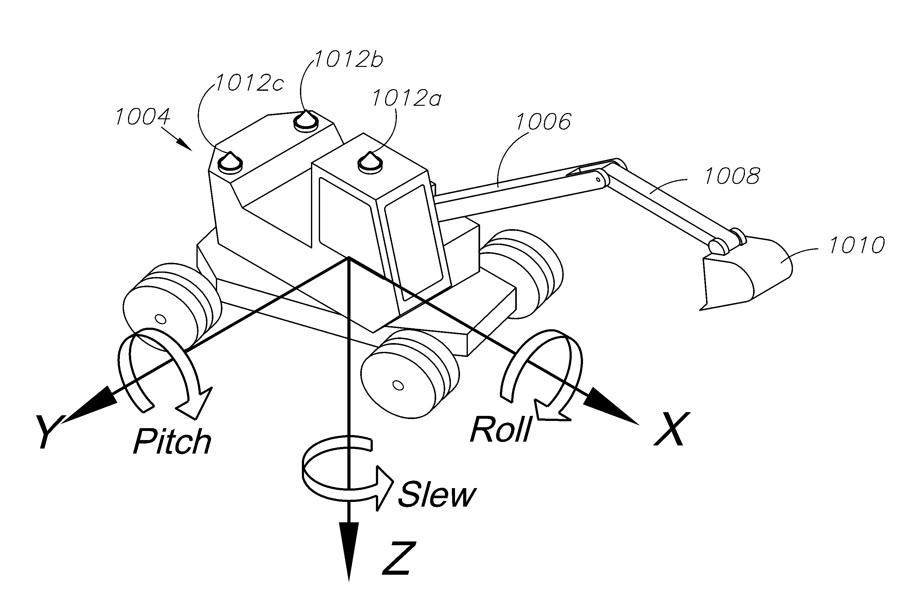
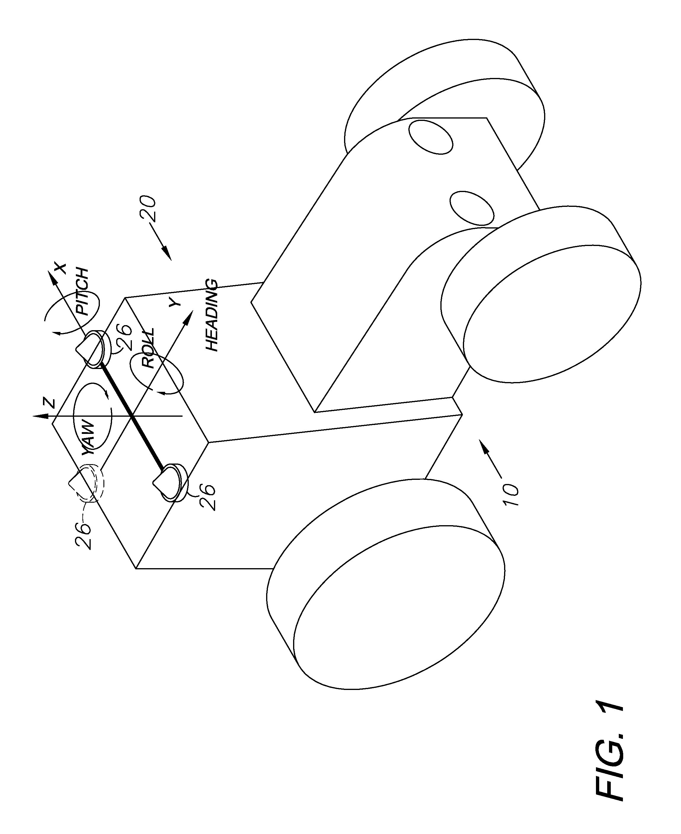
[0062]Global navigation satellite systems (GNSSs) are broadly defined to include GPS (U.S.), Galileo (proposed), GLONASS (Russia), Beidou / Compass (China, proposed), IRNSS (India, proposed), QZSS (Japan, proposed) and other current and future positioning technology using signals from satellites, with or without augmentation from terrestrial sources. Inertial navigation systems (INS) include gyroscopic (gyro) sensors, accelerometers and similar technologies for providing output corresponding to the inertia of moving components in all axes, i.e. through six degrees of freedom (positive and negative directions along X, Y and Z axes). Yaw, pitch and roll refer to moving component rotation about these axes. Said terminology will include the words specifically mentioned, derivatives thereof and words of similar meaning.
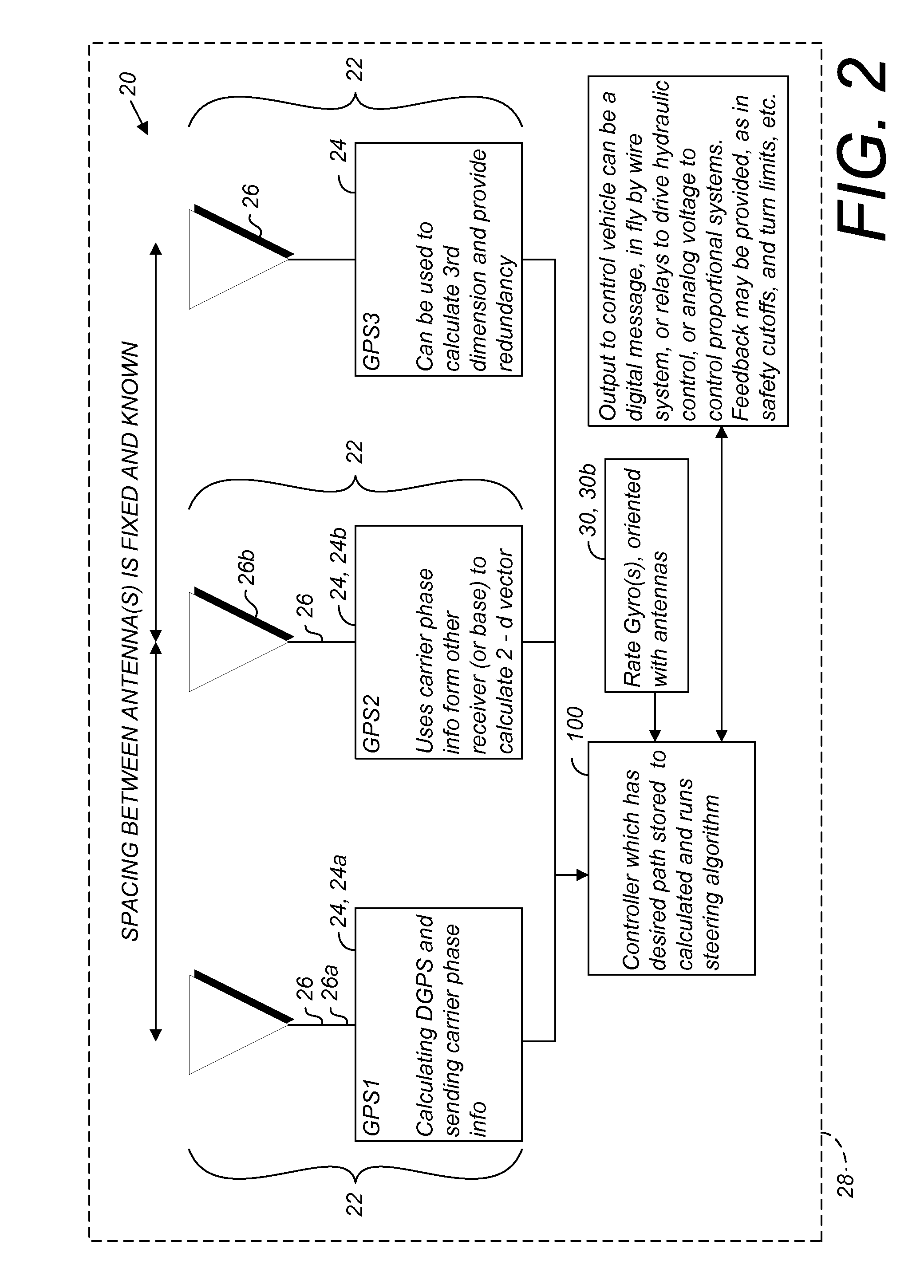
[0063]Disclosed herein in an exemplary embodiment is a sensor system for vehicle guidance. The sensor system utilizes a plurality of GNSS carrier phase d...
PUM
Abstract
A global navigation satellite sensor system (GNSS) and gyroscope control system for vehicle steering control comprising a GNSS receiver and antennas at a fixed spacing to determine a vehicle position, velocity and at least one of a heading angle, a pitch angle and a roll angle based on carrier phase position differences. The roll angle facilitates correction of the lateral motion induced position errors resultant from motion of the antennae as the vehicle moves based on an offset to ground and the roll angle. Alternative aspects include multiple-antenna GNSS guidance methods for high-dynamic roll compensation, real-time kinematic (RTK) using single-frequency (L1) receivers, fixed and moving baselines between antennas, multi-position GNSS tail guidance (“breadcrumb following”) for crosstrack error correction, guiding multiple vehicles and pieces of equipment relative to each other, and snow grooming equipment and method applications.
Description
CROSS-REFERENCE TO RELATED APPLICATIONS[0001]This application is a continuation-in-part of and claims the benefit of U.S. patent application Ser. No. 12 / 857,298, filed Aug. 16, 2010, which is a continuation-in-part of U.S. patent application Ser. No. 12 / 355,776, filed Jan. 17, 2009, now U.S. Pat. No. 8,140,223, which is a continuation-in-part of U.S. patent application Ser. No. 12 / 171,399, filed Jul. 11, 2008 now U.S. Pat. No. 8,265,826, which is a continuation-in-part of U.S. patent application Ser. No. 10 / 804,758, filed Mar. 19, 2004, now U.S. Pat. No. 7,400,956, which is a continuation-in-part of U.S. patent application Ser. No. 10 / 828,745, filed Apr. 21, 2004, now abandoned, and U.S. Provisional Patent Applications No. 60 / 456,146, filed Mar. 20, 2003 and No. 60 / 464,756, filed Apr. 23, 2003. The contents of all of the aforementioned applications are incorporated by reference herein in their entireties.BACKGROUND OF THE INVENTION[0002]This invention relates generally to machine co...
Claims
Application Information
Patent Timeline
Application Date:The date an application was filed.
Publication Date:The date a patent or application was officially published.
First Publication Date:The earliest publication date of a patent with the same application number.
Issue Date:Publication date of the patent grant document.
PCT Entry Date:The Entry date of PCT National Phase.
Estimated Expiry Date:The statutory expiry date of a patent right according to the Patent Law, and it is the longest term of protection that the patent right can achieve without the termination of the patent right due to other reasons(Term extension factor has been taken into account ).
Invalid Date:Actual expiry date is based on effective date or publication date of legal transaction data of invalid patent.