Plate and gasket for plate heat exchanger

a technology of heat exchanger and plate, which is applied in the direction of heat exchanger fastening, light and heating apparatus, laminated elements, etc., can solve the problem of having to reduce the heat transfer region of the plate, and achieve the effect of increasing performance, reducing the number of plates, and ensuring the same capacity

Active Publication Date: 2014-02-11
ALFA LAVAL CORP AB
View PDF15 Cites 29 Cited by
  • Summary
  • Abstract
  • Description
  • Claims
  • Application Information

AI Technical Summary

Benefits of technology

[0006]The object of the invention is to prevent or at least reduce the disadvantages indicated above and provide a better solution for a heat exchanger plate which comprises a gasket and a gasket groove. Particular aims are a new and better heat exchanger plate and a gasket which enables optimum utilisation of the plate's heat transfer region and thereby results in better plate heat exchanger performance with a given number of plates.
[0008]The invention makes it possible to provide a heat exchanger plate where a larger proportion of the plate's surface can be utilised for heat transfer.
[0015]The invention makes it possible to produce a heat exchanger of increased performance. The number of plates can be reduced while maintaining the same capacity, resulting in cost savings on both material and space. Since many applications, e.g. those for aggressive media, involve very expensive material, the heat transfer capacity and hence the number of heat exchanger plates are of crucial cost significance. It is not unusual for a plate heat exchanger to comprise up to a thousand heat exchanger plates, which means that even a seemingly slight capacity improvement of a heat exchanger plate and a plate heat exchanger according to the invention may have a very large impact on profitability.

Problems solved by technology

A consequent disadvantage is that the heat transfer region of the plate has to be made smaller than it would be if the gasket groove was instead positioned relative to the retraction along the heat transfer region, since that retraction is smaller.

Method used


Image

  • Plate and gasket for plate heat exchanger
  • Plate and gasket for plate heat exchanger
  • Plate and gasket for plate heat exchanger

Examples


second embodiment

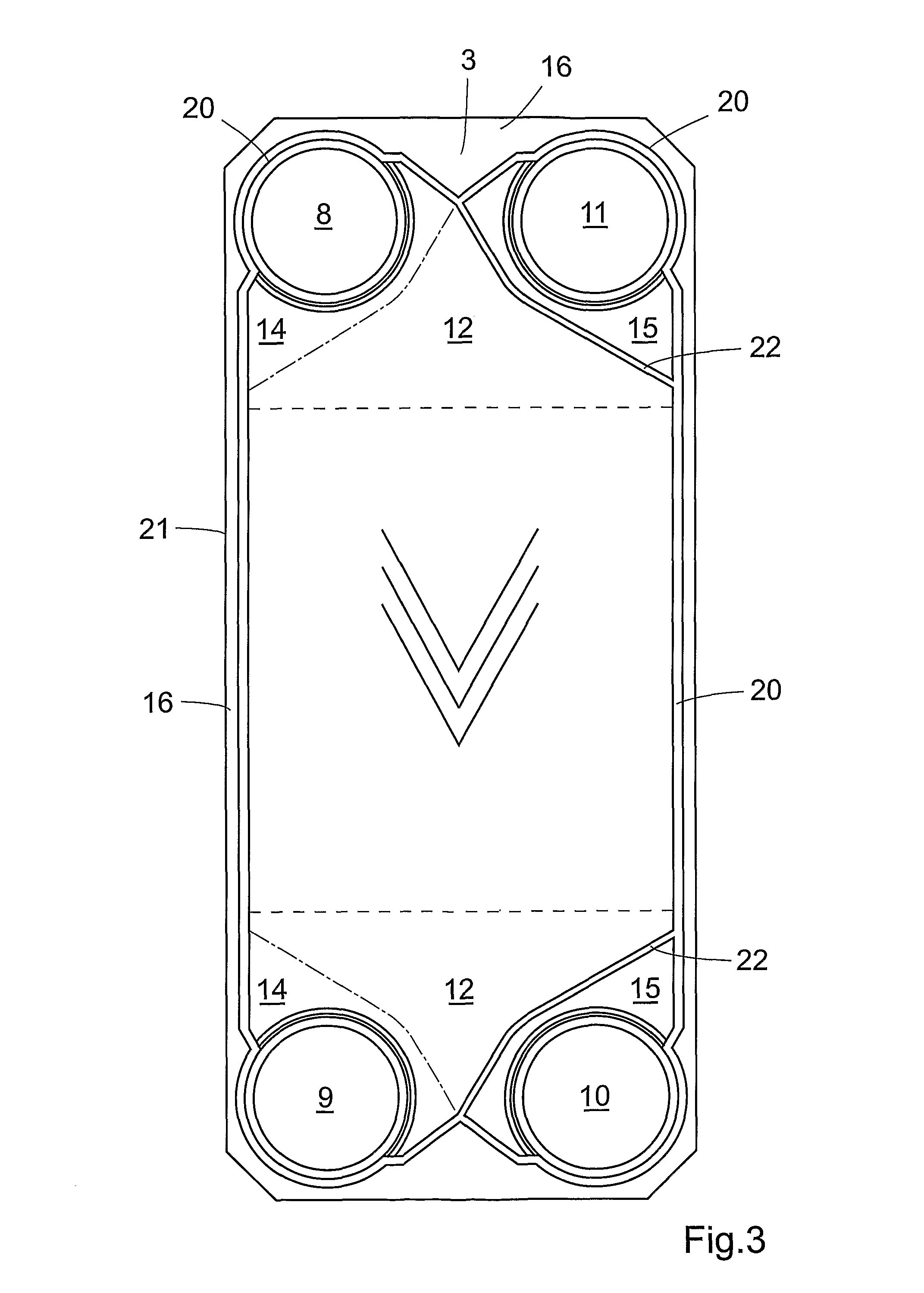
[0038]According to the invention, the first gasket groove 20, at the end 20C′ of the third portion 20C which points towards the heat transfer region 13, connects to the second gasket groove 22 at a point P1 which divides the second gasket groove 22 into a first section 22A extending between the centreline L and the point P1, and a second section 22B extending between the point P1 and the first gasket groove 20 at an end 20D′ of the fourth portion 20D.

[0039]Positioning the first gasket groove 20 at the third portion 20C along the second adiabatic region 15 somewhat further in on the heat exchanger plate 3, nearer to the centreline L, makes it possible to cater for the fact that there will be greater retraction of the heat exchanger plate along this edge section. The advantage is that the plate's heat transfer region 13 can be made larger than it would be if the first gasket groove 20 at the fourth portion 20D was instead positioned in relation to the retraction along the adiabatic re...

third embodiment

[0040]In the invention, two heat exchanger plates 3 are joined together permanently as a pair to form a cassette, e.g. by welding. Gaskets 19 are with advantage disposed between adjacent cassettes.

[0041]As mentioned above, gaskets 19 are fitted between two adjacent heat exchanger plates 3, or between two cassettes, before assembling the plate heat exchanger 1, and the shape of the gasket 19 corresponds in principle to the shape and extent of the gasket grooves 20, 22, as may be seen in FIGS. 5 and 7. The gasket is usually made of a rubber or polymer material.

first embodiment

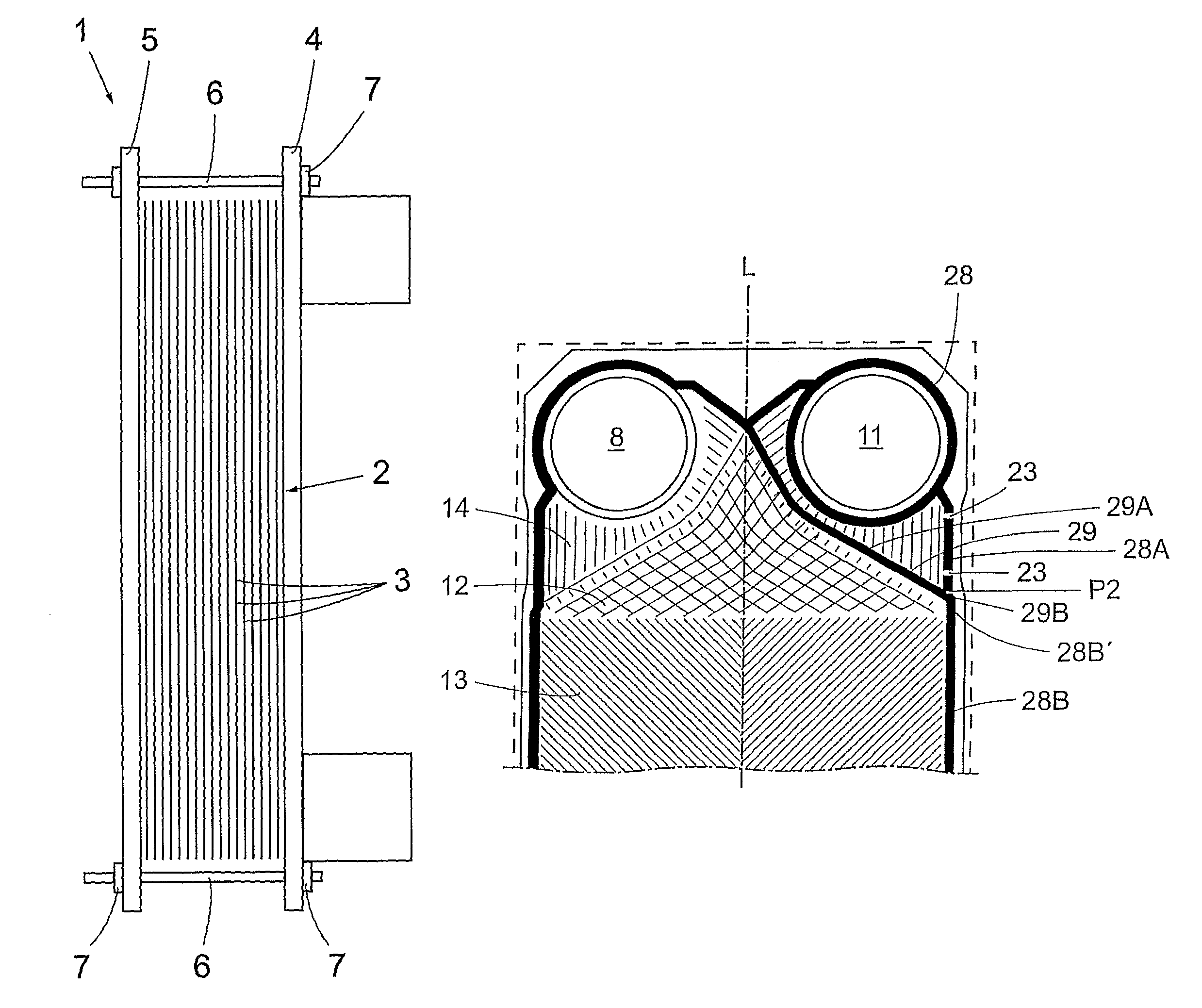
[0042]According to the gasket 19 according to the invention, it comprises a first gasket part 28 to be accommodated in the gasket groove 20 and a second gasket part 29 to be accommodated in the gasket groove 22. The gasket part 28 extends in a section 28a along the adiabatic region 15 at a distance from a centreline L in the longitudinal direction of the heat exchanger plate 3 which is less than the distance from the first gasket part 28 in a section 28B along the heat transfer region 13 to the heat exchanger plate centreline L.

[0043]According to another embodiment, the gasket part 28, at an end 28A′ of the section 28A which points towards the heat transfer region 13, connects to the second gasket part 29 at a point P2 which divides the gasket part 29 into a first section 29A extending between the centreline L and the point P2, and a second section 29B extending between the point P2 and the gasket groove 28 at an end 28B′ of the section 28B.

[0044]To be able to transfer leaking mediu...


PUM


Abstract

The invention relates to a heat exchanger plate for a plate heat exchanger, which plate has a number of ports, a distribution region, a heat transfer region, a first adiabatic region, a second adiabatic region and an edge area that extends outside the ports and the regions, which plate has a first gasket groove extending in the edge area outside the regions and around the ports, and a second gasket groove extending between the adiabatic region and the adjacent distribution region, whereby the gasket grooves are connected together to accommodate a gasket for sealing abutment against an adjacent heat exchanger plate in the plate heat exchanger. The invention further relates to a gasket for a heat exchanger plate and a plate heat exchanger having a package of heat exchanger plates and gaskets.

Description

FIELD OF THE INVENTION[0001]The present invention relates to a heat exchanger plate for a plate heat exchanger according to the preamble of claim 1. The invention also relates to a gasket for the heat exchanger plate and a plate heat exchanger comprising the heat exchanger plate and the gasket according to the invention.STATE OF THE ART[0002]Plate heat exchangers provided with gaskets normally comprise a package of heat exchanger plates disposed adjacent to one another. Gaskets are disposed between the heat exchanger plates, or the plates are permanently joined together, e.g. by soldering. The plates may also be permanently joined together in pairs to form so-called cassettes, e.g. by welding, with gaskets placed between the respective cassettes. The gaskets are accommodated in gasket grooves formed during the form-pressing of the heat exchanger plates. Plate heat exchangers further comprise inlet and outlet ports, which extend through the plate package, for two or more media.[0003]...

Claims


Application Information

Patent Timeline
Patent Type & Authority Patents(United States)
IPC IPC(8): F28F3/08
CPCF28F3/10F28F3/046F28F2230/00F28D9/005F28F2275/06F28F9/026F28F3/083F28F3/02B21D53/04F28D9/00F28F3/04F28F3/08F28F9/02
Inventor BLOMGREN, RALF
Owner ALFA LAVAL CORP AB
Why Eureka
Try Eureka