Ionization gauge with operational parameters and geometry designed for high pressure operation

a technology of ionization gauge and operational parameters, applied in the direction of fluid pressure measurement, discharge tube main electrode, instruments, etc., can solve the problems of reducing the emission characteristics of electron sources, reducing the operational life, and complete burnout of tungsten cathodes, so as to reduce the number of electrons generated and reduce the operational life

Active Publication Date: 2014-02-11
MKS INSTR INC
View PDF25 Cites 15 Cited by
  • Summary
  • Abstract
  • Description
  • Claims
  • Application Information

AI Technical Summary

Benefits of technology

[0005]The operational lifetime of a typical ionization gauge is approximately ten years when the gauge is operated in benign environments. However, these same gauges and electron sources (cathodes) fail in minutes or hours when operated at too high a pressure or during operation in gas types that degrade the emission characteristics of the electron source. Cathode interactions with the gauge environment can lead to decreased operational life. The oxide coating on the cathode can degrade when exposed to water vapor. Degradation of the oxide coating dramatically reduces the number of electrons generated by the cathode. Exposure to water vapor results in the complete burnout of a tungsten cathode.
[0006]Sputtering is also a problem, when operating the ionization gauge at high pressures, such as above 10−4 Torr. This is a problem at high pressure since there is more gas to ionize. This sputtering is caused by high impact energies between ions and components of the ionization gauge as has been demonstrated by the inventor. Ions with a high energy may impact a tungsten material that forms a collector post of the ionization gauge. This results in atoms being ejected from the collector post and envelope surfaces. This ejection carries a significant internal kinetic energy. Ejected material can travel freely to other surfaces within the line of sight of the material, and can cause gauge failure by coating the cathode or by coating of the feed-through insulators of the gauge, which can result in electric leakages.
[0007]The kinetic energy of the ions generated in a Bayard-Alpert ionization gauge is determined by a difference in the bias voltages between an anode grid and a collector post electrode. A bias voltage of a cathode is typically at 30 volts, and a bias voltage of the anode grid is traditionally operated at 180 volts. The collector voltage is usually fixed at a ground potential, or at a voltage near a ground potential. These voltage differentials are configured to provide 150 electron volts (eV) amount of energy for the electrons. This amount is capable of efficiently ionizing all gas species present in the gauge ionization volume. This potential difference also assures efficient transport of the electrons from the cathode to the anode volume. Efficient ionization is needed to assure an adequate signal to noise ratio from the collector at low gas density levels.

Problems solved by technology

However, these same gauges and electron sources (cathodes) fail in minutes or hours when operated at too high a pressure or during operation in gas types that degrade the emission characteristics of the electron source.
Cathode interactions with the gauge environment can lead to decreased operational life.
Exposure to water vapor results in the complete burnout of a tungsten cathode.
Sputtering is also a problem, when operating the ionization gauge at high pressures, such as above 10−4 Torr.
This is a problem at high pressure since there is more gas to ionize.
This results in atoms being ejected from the collector post and envelope surfaces.
Ejected material can travel freely to other surfaces within the line of sight of the material, and can cause gauge failure by coating the cathode or by coating of the feed-through insulators of the gauge, which can result in electric leakages.

Method used


Image

  • Ionization gauge with operational parameters and geometry designed for high pressure operation
  • Ionization gauge with operational parameters and geometry designed for high pressure operation
  • Ionization gauge with operational parameters and geometry designed for high pressure operation

Examples


Embodiment Construction

[0034]A description of preferred embodiments of the invention follows.

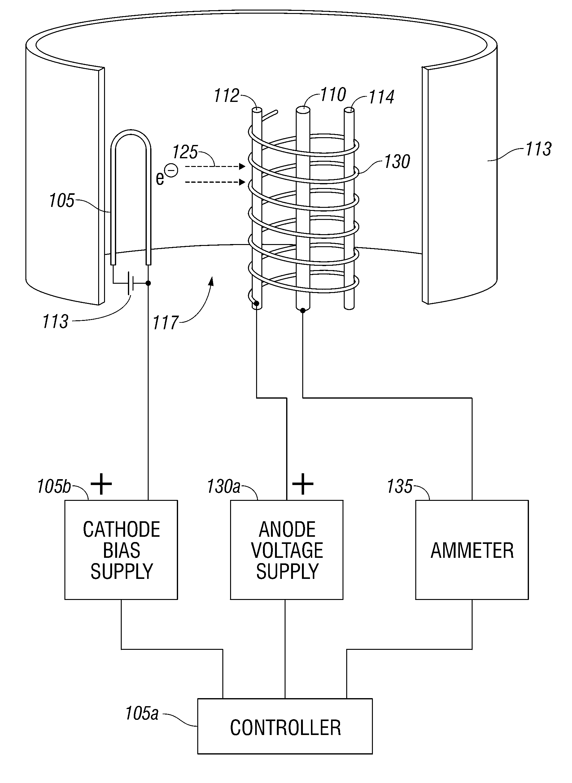
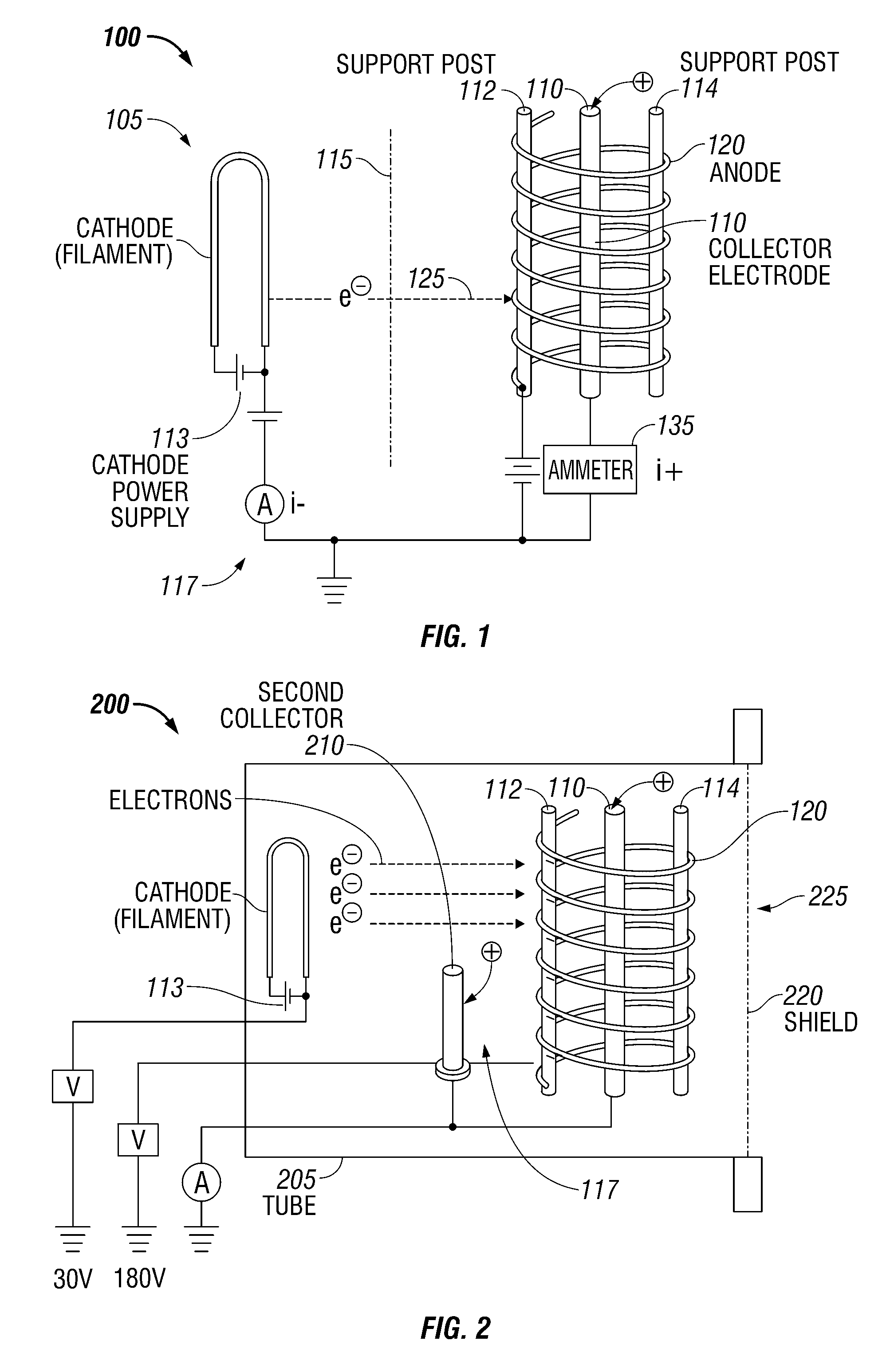
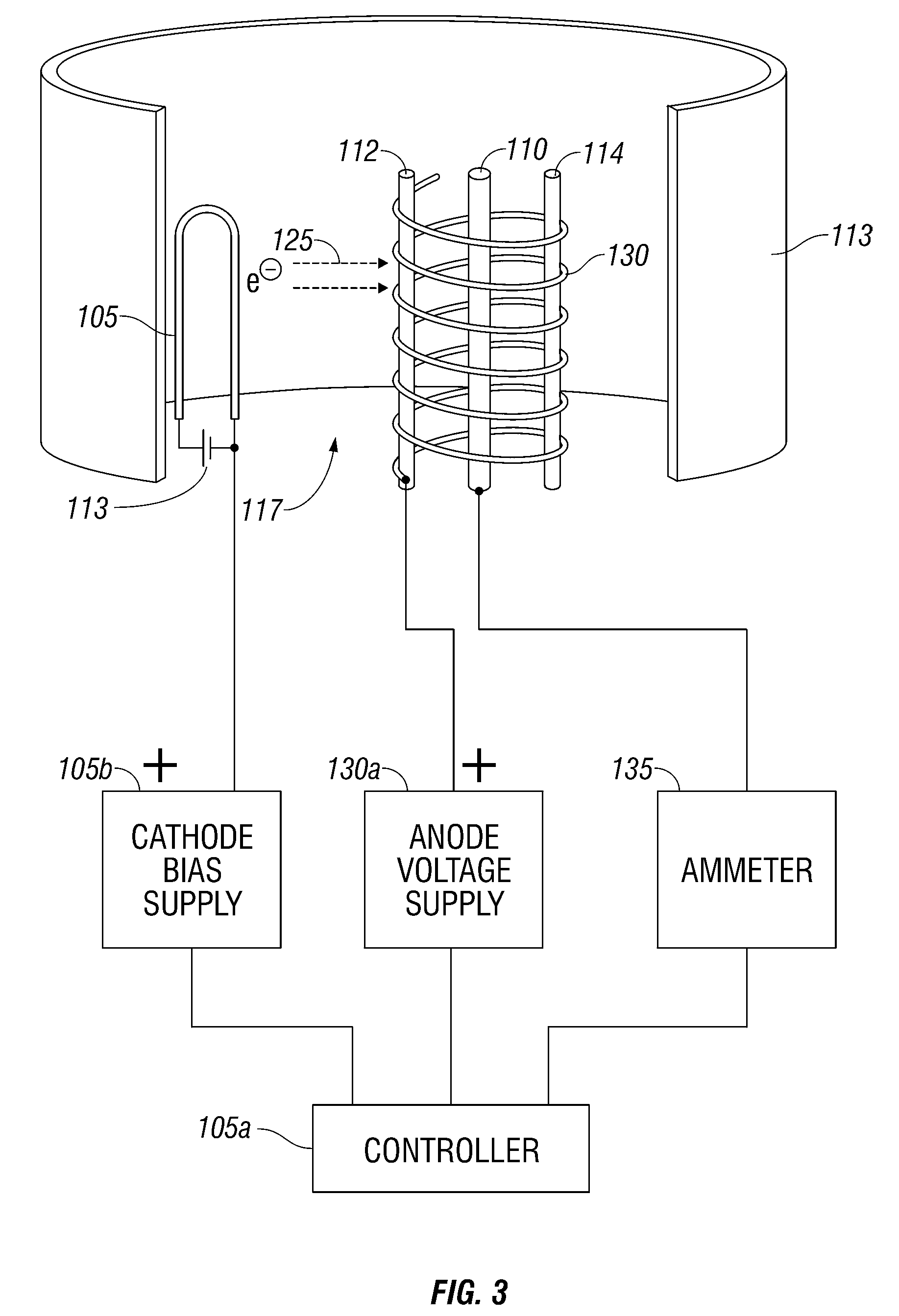
[0035]Generally, as shown in FIG. 1, an ionization gauge 100 of the present disclosure has at least one electron source 105 and at least one collector electrode 110. The electron source 105 may be separated from the at least one collector electrode 110 by an optional isolation material 115 which prevents molecules and atoms of gas within a measurement chamber 117 from degrading the electron source(s) 105. The ionization gauge 100 also includes an ionization volume and specifically an anode 120. Anode 120 and the collector electrode 110 components may have various different configurations, and the gauge 100 is not limited to FIG. 1. In one embodiment, the ionization gauge 100 is a Bayard-Alpert type gauge, or an ionization gauge 100 where a heated cathode 105 is used to emit electrons toward an anode grid volume 120. However, it should be appreciated that the gauge 100 is not limited to any specific ionization gaug...


PUM

PropertyMeasurementUnit
bias voltageaaaaaaaaaa
pressuresaaaaaaaaaa
bias voltageaaaaaaaaaa

Abstract

An ionization gauge to measure pressure and to reduce sputtering yields includes at least one electron source that generates electrons. The ionization gauge also includes a collector electrode that collects ions formed by the collisions between the electrons and gas molecules. The ionization gauge also includes an anode. An anode bias voltage relative to a bias voltage of a collector electrode is configured to switch at a predetermined pressure to decrease a yield of sputtering collisions.

Description

RELATED APPLICATIONS[0001]This application is a continuation of International Application No. PCT / US2009 / 034460, which designated the United States and was filed on Feb. 19, 2009, published in English, which application claims the benefit of U.S. Provisional Application No. 61 / 066,631, filed on Feb. 21, 2008.[0002]The entire teachings of the above applications are incorporated herein by reference.BACKGROUND OF THE INVENTION[0003]Ionization gauges, more specifically Bayard-Alpert (BA) ionization gauges, are the most common non-magnetic means of measuring very low pressures. The gauges have been widely used worldwide. These gauges were disclosed in 1952 in U.S. Pat. No. 2,605,431, which is herein incorporated by reference in its entirety. A typical ionization gauge includes an electron source, an anode, and an ion collector electrode. For the BA ionization gauge, the electron source is located outside of an ionization space or anode volume which is defined by a cylindrical anode scree...

Claims


Application Information

Patent Timeline
Patent Type & Authority Patents(United States)
IPC IPC(8): G01L21/30
CPCG01L21/32G01L21/34H01J41/02G01L21/30
Inventor BRUCKER, GERARDO A.
Owner MKS INSTR INC
Why Eureka
Try Eureka