
Filter, portable terminal and electronic component

Inactive Publication Date: 2014-02-11
NDK SAW DEVICES CO LTD
View PDF30 Cites 2 Cited by
  • Summary
  • Abstract
  • Description
  • Claims
  • Application Information

AI Technical Summary

Benefits of technology

The present invention provides a filter that has a low loss in a required pass band and a large attenuation in multiple attenuation bands outside the pass band. This, in addition to reducing the number of inductors for phase inversion, contributes to the miniaturization of the device. The filter is suitable for portable terminals and can prevent interference from transmission waves to reception waves, such as TV tuners.

Problems solved by technology

As already described above, the antennas are closely disposed and in a case that bands of transmission / reception waves are close to each other, there occurs a problem that a transmission wave of audio or data communication reaches the digital TV broadcast reception antenna via the antenna thereby giving interference to a weak reception wave of TV broadcast.
However, a module mounted in a portable terminal is restricted in terms of a mounting area and a space, and the above constitution has its limit.
Further, since the reception band of digital TV broadcast and the transmission band of audio or data are quite close to each other, a steep attenuation characteristic is necessary.
However, it is difficult to obtain a broad pass band and a large attenuation amount by constituting the SAW filter by an SAW resonator alone.
When the inductor is to be created according to a wiring pattern, it is necessary to bend a large pattern and to make a film thickness large, making a conductor loss large and lowering a Q value.
As can be known from this diagram, when the mount number of the external coils is large the size of the device becomes large, which is a large cause for hampering miniaturization of the device.

Method used


Image

  • Filter, portable terminal and electronic component
  • Filter, portable terminal and electronic component
  • Filter, portable terminal and electronic component

Examples


first embodiment

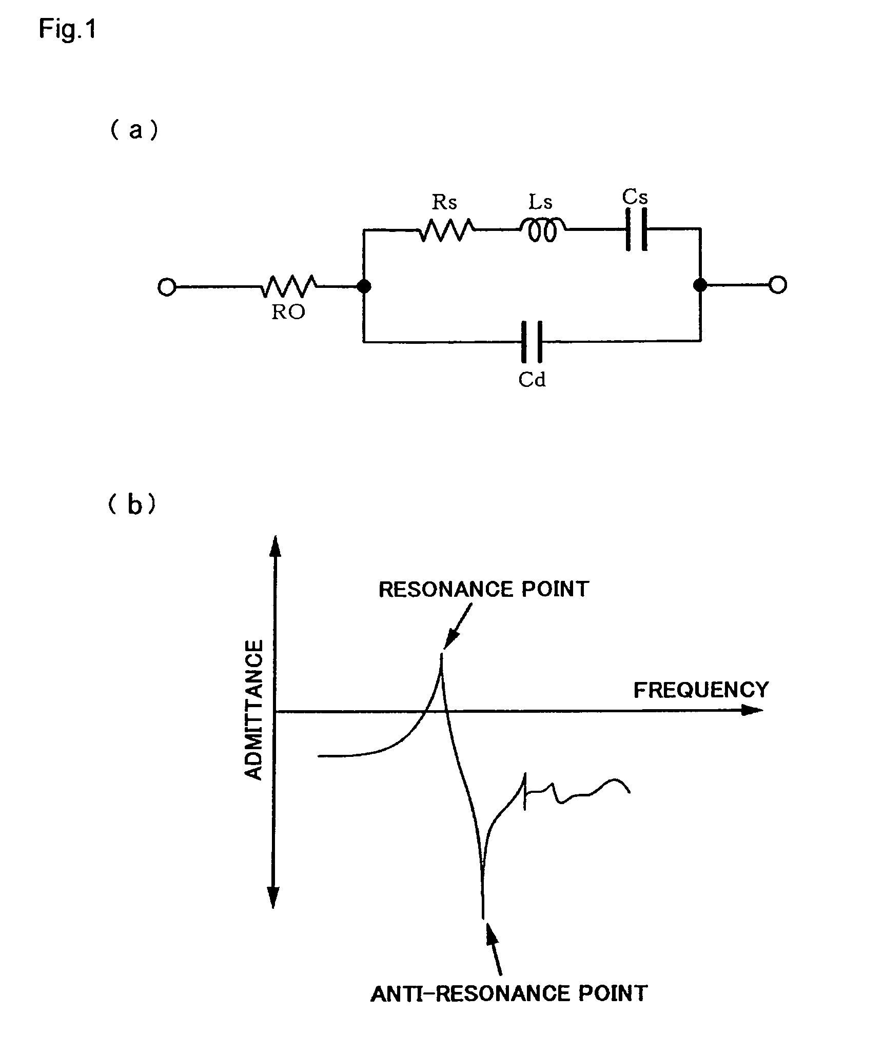
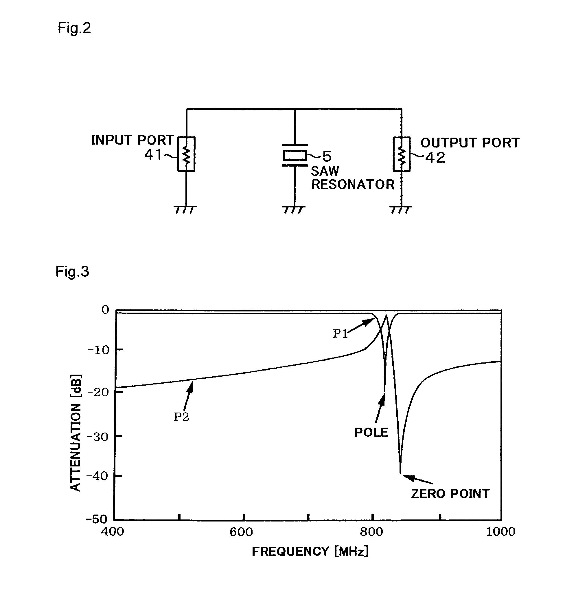
[0068]Before describing embodiments of the present invention, a background leading to a constitution of the present invention, a reason that a transmission characteristic responding to the above-described request can be obtained, and the like will be stated. FIG. 1(a) shows an equivalent circuit of an SAW resonator being an elastic wave resonator, while FIG. 1(b) shows an admittance characteristic for a frequency of the SAW resonator. A reference symbol Rs indicates a series resistance (active resistance), a reference symbol Ls indicates a series inductance (active inductance), a reference symbol Cs indicates a series capacitance (active capacitance), a reference symbol Cd indicates an electrode capacitance (control capacitance), and a reference symbol RO indicates an external resistance. Since the SAW resonator has such an admittance characteristic, when a filter is constituted as shown in FIG. 2 by providing an SAW resonator 5 as a parallel arm between an input port 41 and an outp...

second embodiment

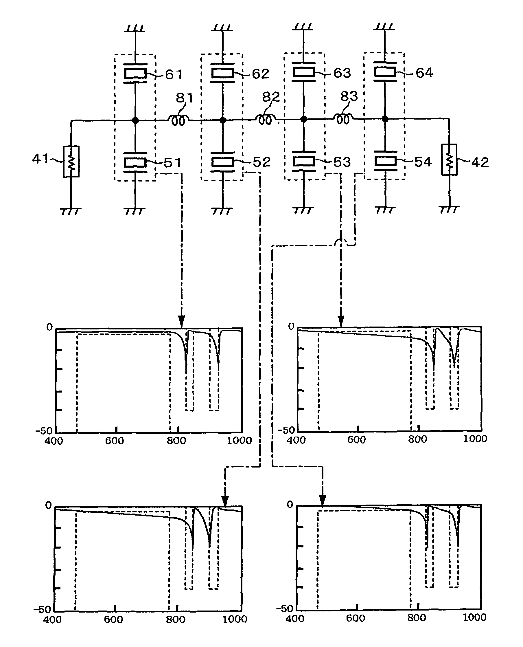
[0082]Further, in the present invention, in a case that a signal level is to be attenuated in a first attenuation band and a second attenuation band, a constitution shown in FIG. 21 can be adopted. In this circuit sets of SAW resonators shown in FIG. 14 described above are connected in three stages, and in addition, another set of SAW resonators is prepared and one and the other of two SAW resonators 54, 64 constituting the set are connected in parallel to inductors 81, 82 respectively. Then, those parallel circuits 810 and 820 are constituted to resonate in parallel in the first attenuation band and the second attenuation band respectively. It should be noted that in the parallel circuits 810 and 820 resonance frequencies can slightly depart from the first attenuation band and the second attenuation band respectively as long as obtained transmission characteristics are satisfying.

[0083]In other words, the circuit shown in FIG. 21 is to secure an attenuation amount by resonating the...

third embodiment

[0084]In the first embodiment, it is constituted that the sets of the plural SAW resonators, of two resonators for example, which are connected to the same electric potential point in the signal path, are connected in the plural stages, in two stages for example, via the inductor. In contrast, in a third embodiment, a series circuit in which a plurality of SAW resonators are connected to each other in series is constituted as a parallel arm, and sets of SAW resonators being the parallel arms are connected in a plurality of stages via an inductor.

[0085]FIG. 23 shows an SAW filter constituted by connecting two SAW resonators 5, 6 to the same electric potential point in a signal path as a parallel arm, to the SAW filter resonance points different from each other being set so that steep attenuation amounts can be obtained in respective two attenuation bands close to each other. FIG. 24 shows a transmission characteristic in the SAW filter of FIG. 23, and it can be known that poles exist...


PUM


Abstract

An object is to obtain a steep and large attenuation amount in attenuation bands close to each other out of a band of a TV wave and to provide a filter in which the use number of inductors is reduced thereby to be able to contribute to downsizing of a device. Elastic wave resonators of a plurality of parallel arms for each forming plurality of attenuation band are connected to the same electric potential point in a signal path without aid of an inductor. Otherwise, a series circuit of a plurality of element parts generating series resonance is connected in a signal path as a parallel arm. Therefore, a large attenuation amount can be obtained in each of the plural attenuation bands, but a region equivalent to what is called a zero point exists between adjacent poles. However, there can be obtained a characteristic in which steep attenuations occur in both sides of the zero point even if the zero point exists. Sets of elastic wave resonators (sets of resonators) connected to the same potential points or parallel arms constituted by the series circuits are connected in a signal path in a plurality of stages, and an inductor for inverting a phase intervenes between the stages.

Description

TECHNICAL FIELD[0001]The present invention relates to a filter such as an SAW (surface acoustic wave) filter for example, to a portable terminal having a digital terrestrial TV reception device for example in which the filter is used, and to an electronic component in which the filter is used.BACKGROUND ART[0002]Digital terrestrial broadcast in Japan began in 2003, and a service of digital terrestrial broadcast began in Europe and other districts from 2000. Meanwhile, as portable terminals become popular, there have been provided various high value added services such as a mail function in comparison with a telephone function of a conventional portable terminal. In such a trend, portable terminal manufacturers in the world consider to bring in a service of receiving digital terrestrial broadcast by giving a portable terminal a reception function of digital terrestrial TV broadcast in addition to a conventional portable telephone function thereby to make a portable terminal with a di...

Claims


Application Information

Patent Timeline
IPC IPC(8): H03H9/46H03H7/01H03H9/54H03H9/64
CPCH03H9/542H03H9/6483H03H7/1758H03H9/605H03H7/075H03H9/6409H03H9/547
Inventor ONZUKA, TATSUNORI
Owner NDK SAW DEVICES CO LTD
Learn More