Prismatic multiple waveguide for near-eye display

a near-eye display and waveguide technology, applied in the field of near-eye displays, can solve the problems of limited parallelity between multiple waveguides, and achieve the effect of constant grazing angles

Active Publication Date: 2014-02-11
VUZIX
View PDF5 Cites 134 Cited by
  • Summary
  • Abstract
  • Description
  • Claims
  • Application Information

AI Technical Summary

Benefits of technology

[0013]Preferably, the input and output couplings operate without contributing optical power. Nonetheless, the distribution of the different angle beamlets among the waveguides enables the different angle beamlets to converge from the output coupling to the eyebox and thereby at least partially assemble an exit pupil within the eyebox. Preferred embodiments of the invention improve efficiency by assuring that more of the light entering the waveguides reaches the eyebox.
[0015]Preferably, the output coupling converges the different angular ranges of the beamlets toward the eyebox without contributing optical power that would otherwise affect the angular magnification of the virtual images. The image generator preferably includes an aperture within which the angular transforms of the virtual images overlap, and the optical spacing between the input coupling and the image generator positions the aperture of the image generator at an optical distance from the input coupling so that the angularly related beamlets are partially spatially separated at the input coupling. The different angular ranges of the beamlets are preferably distributed among the waveguides so that the convergence of the different angular ranges of the beamlets from the output coupling reduces the spatial separation between the angularly related beamlets within the eyebox.
[0022]Preferably, the at least partially reflective surfaces at the exit ends of the parallel waveguides are partially transmissive, and also preferably included within the compound waveguide system is a mating prismatic waveguide extender that compensates for refractive effects associated with transmissions through the partially reflective surfaces at the exit ends of the parallel waveguides. The partially reflective surfaces of the prismatic output coupling combined with the mating prismatic waveguide extender allows a user to view the ambient environment through the prismatic output coupling without a significant shift of the view.

Problems solved by technology

Although composed of multiple waveguides, the overall thickness of the multiple waveguides is not appreciably more than the thickness of a single waveguide required to convey the entire angular range of beamlets and the parallelism within which the multiple waveguides must be related is limited by the prescribed optical isolation between the waveguides.

Method used


Image

  • Prismatic multiple waveguide for near-eye display
  • Prismatic multiple waveguide for near-eye display
  • Prismatic multiple waveguide for near-eye display

Examples


Embodiment Construction

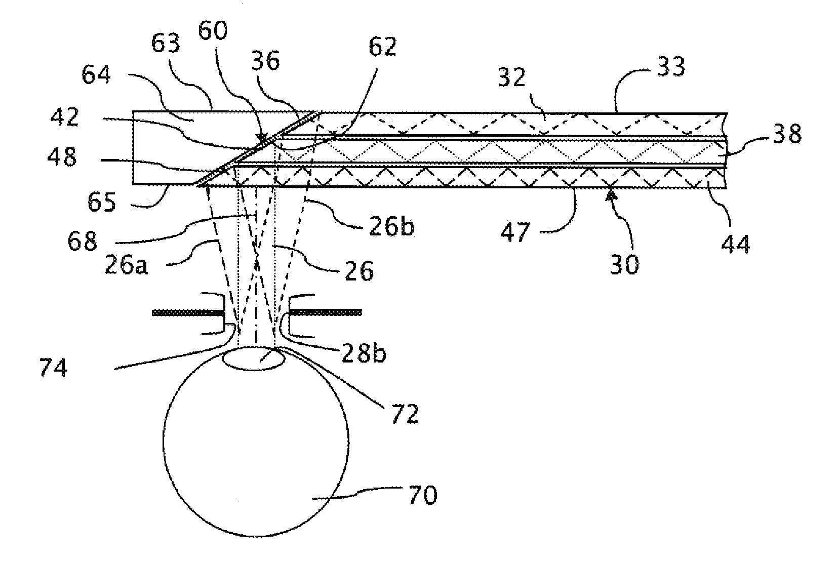
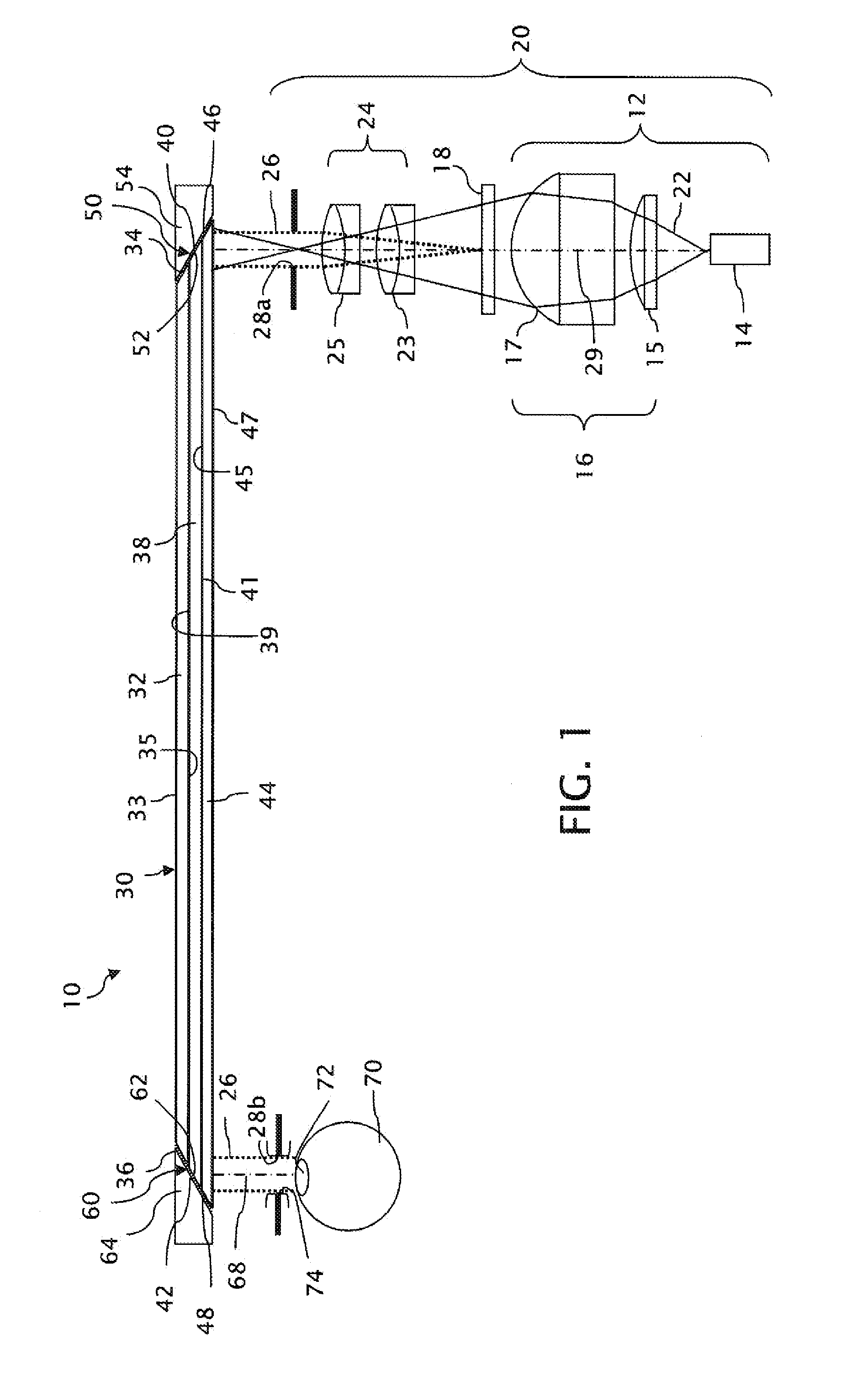
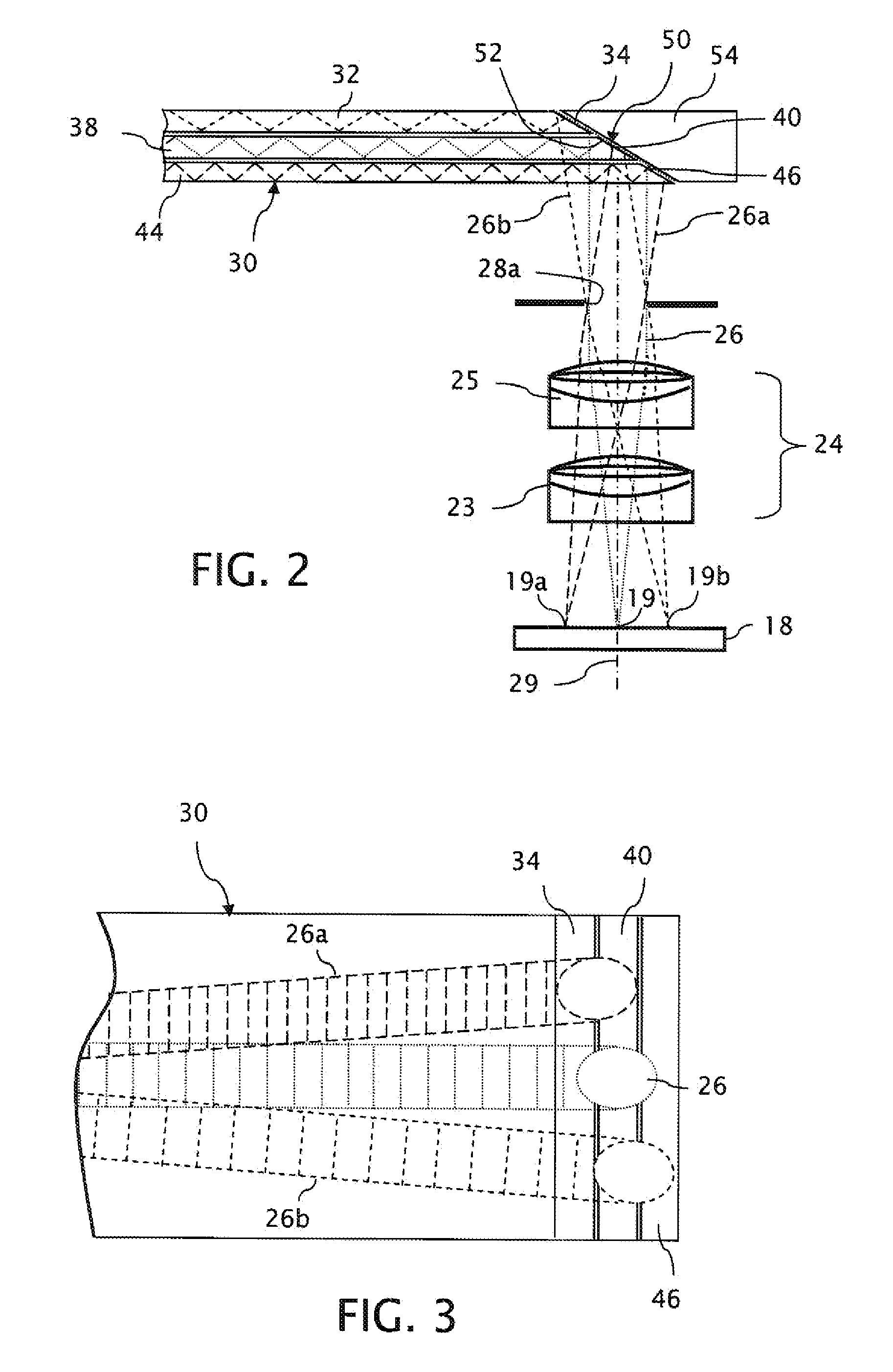
[0040]A general optical layout of a near-eye display 10 arranged in accordance with the invention is shown in FIG. 1. The near-eye display 10 includes an image generator 20 for generating angular transforms of virtual images intended for display and a compound optical waveguide 30 for conveying the output of the image generator 20 from outside a viewer's field of view into alignment with the viewer's field of view.

[0041]The image generator 20 is based on a spatial light modulator 18, which produces light patterns in accordance with a video input signal (not shown). An illuminator 12, which includes a light source 14 and a condenser 16, uniformly illuminates the spatial light modulator 18. The light source 14, which emits an expanding light beam 22, can be formed by one or more light emitting diodes or other sources including lamps known for illuminating spatial light modulators or other microdisplay engines. The condenser 16 includes one or more optical elements, such as a PCX (pian...


PUM

PropertyMeasurementUnit
distanceaaaaaaaaaa
refractive indexaaaaaaaaaa

Abstract

A near-eye display includes a compound waveguide for presenting viewers with virtual images visible within an eyebox at a limited relief distance from the compound waveguide. The compound waveguide is assembled from a plurality of waveguides that are at least partially optically isolated for conveying different portions of the virtual image. An input couple injects the different portions of the virtual image into predetermined combinations of the waveguides, and an output coupling ejects the different portions of the virtual image from the waveguides toward the eyebox in a form that at least partially constructs a pupil within the eyebox.

Description

TECHNICAL FIELD[0001]The invention relates to near-eye displays that include waveguides for conveying image information in a compact form to viewers' eyes, particularly as information for forming virtual images within viewers' eyes.BACKGROUND OF THE INVENTION[0002]Waveguides of near-eye displays convey image information toward viewers' eyes from positions outside the viewers' fields of view. The image information conveyed by many such waveguides has an angularly encoded form for projecting virtual images into the viewers' eyes. The near-eye displays present the image information to the viewers within viewing pupils (also referred to as “eyeboxes”), which when aligned with the pupils of the viewers' eyes produce virtual images within the viewer's fields of view.[0003]The image information originates outside the viewers' fields of view in positions such as along the temples of eyeglass frames. Electronic video display data is converted into the image information by optical pattern gen...

Claims


Application Information

Patent Timeline
Patent Type & Authority Patents(United States)
IPC IPC(8): G02B27/14
CPCG02B2027/0125G02B6/00G02B27/0101B29D11/00663Y10T156/10
Inventor SCHULTZ, ROBERT J.BURDICK, NATHAN E.
Owner VUZIX
Why Eureka
Try Eureka