Lightning-protection fastener
a technology of protection and fasteners, applied in the field of fasteners, can solve the problems of the insulation cap falling off from the fastener head portion, and achieve the effects of reducing fuel consumption, preventing the peeling off during the operation of the aircraft, and increasing thickness
- Summary
- Abstract
- Description
- Claims
- Application Information
AI Technical Summary
Benefits of technology
Problems solved by technology
Method used
Image
Examples
first embodiment
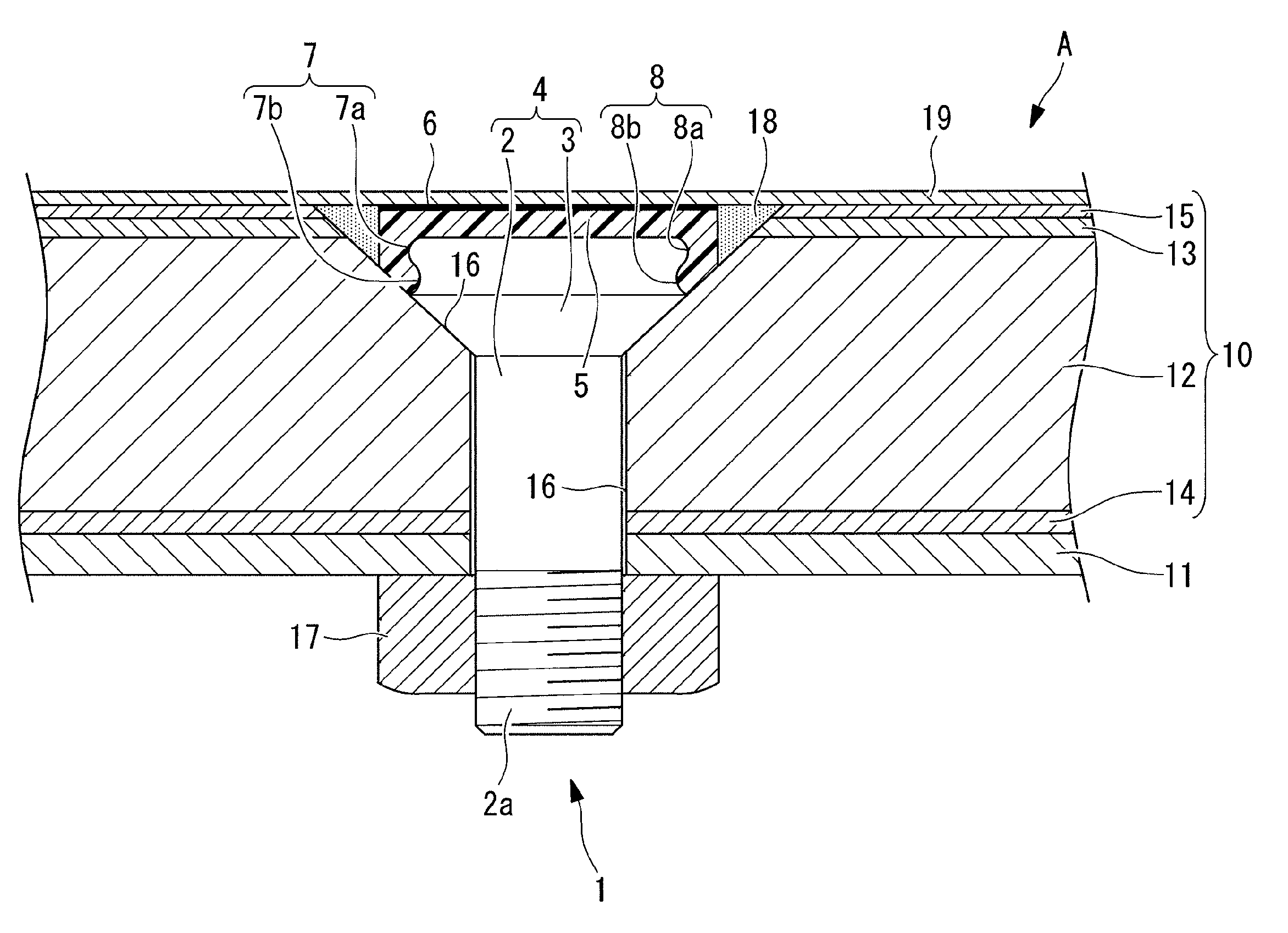
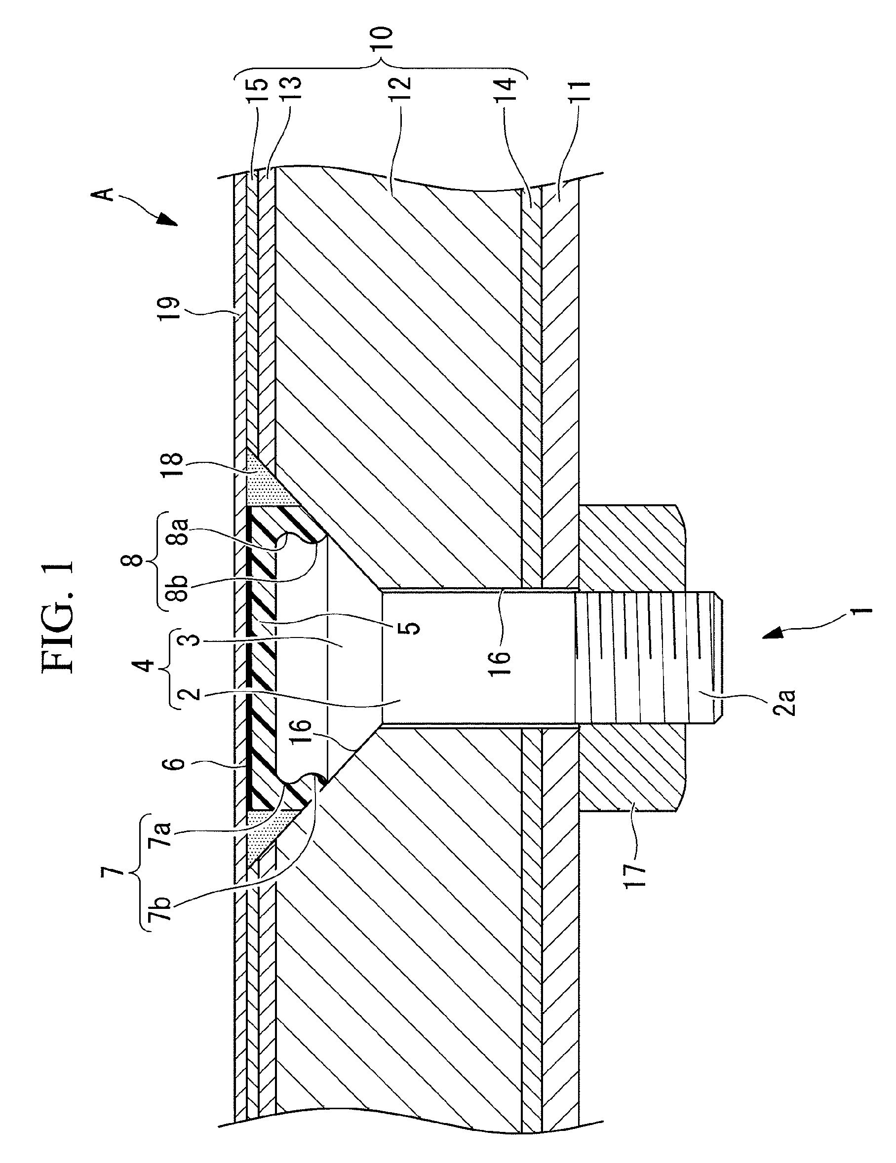
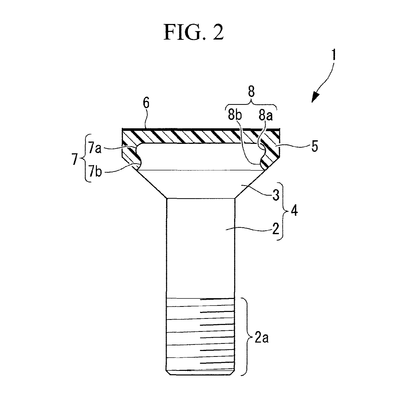
[0050]a lightning-protection fastener (Fastener) according to the present invention will be described below, referring to FIGS. 1 and 2.
[0051]As shown in FIGS. 1 and 2, a lightning-protection fastener (a fastener of the lightning-protection type) 1 according to this embodiment is constituted mainly of a cylindrical rod-shaped shaft portion (Shank) 2, a fastener main body 4 having a substantially truncated-cone shaped head portion (Flush Head) 3 that is provided at one end of the shaft portion 2 and whose diameter increases with increasing distance from the shaft portion 2, an insulation layer 5 disposed so as to cover one end portion (the top portion located on the top side in FIGS. 1 and 2) of the head portion 3, and a conductive layer 6 disposed so as to cover one end surface (the end surface on the top side in FIGS. 1 and 2) of the insulation layer 5.
[0052]The fastener main body 4 is formed integrally of the shaft portion 2 and the head portion 3 and is manufactured using, for ex...
second embodiment
[0077]a lightning-protection fastener according to the present invention will now be described using FIGS. 3A and 3B.
[0078]A lightning-protection fastener 21 according to this embodiment differs from that in the first embodiment described above in that engagement portions 22 and 23 are provided instead of the engagement portions 7 and 8 described above. Because other components are the same as those in the first embodiment described above, descriptions of those components are omitted herein.
[0079]Note that the identical reference numerals are given to the members identical to those of the first embodiment described above.
[0080]Fastener-side engagement portions (engagement portions) 22, to which the insulation layer 5 is secured, are provided (formed) on one end portion (top portion) of the head portion 3. The fastener-side engagement portions 22 are a plurality (eight in this embodiment) of through-holes penetrating in the plate-thickness direction and are disposed along the circumf...
third embodiment
[0089]a lightning-protection fastener according to the present invention will now be described using FIGS. 4A to 6C.
[0090]The lightning-protection fastener 31 according to this embodiment differs from those of the embodiments described above in that engagement portions 32 and 33 are provided instead of the engagement portions 7, 8, 22, and 23 described above. Because other components are the same as those in the embodiments described above, descriptions of those components are omitted herein.
[0091]Note that the identical reference numerals are given to the members identical to those of the embodiments described above.
[0092]A fastener-side engagement portion (engagement portion) 32, to which the insulation layer 5 is secured, is provided (formed) on the top surface of the head portion 3. The fastener-side engagement portion 32 is provided with a first convex portion 34 having a circular shape in plan view and positioned in the central portion thereof and a second convex portion 35 ha...
PUM
 Abstract
Description
Claims
Application Information
 - R&D
- Intellectual Property
- Life Sciences
- Materials
- Tech Scout
- Unparalleled Data Quality
- Higher Quality Content
- 60% Fewer Hallucinations
Browse by: Latest US Patents, China's latest patents, Technical Efficacy Thesaurus, Application Domain, Technology Topic, Popular Technical Reports.
© 2025 PatSnap. All rights reserved.Legal|Privacy policy|Modern Slavery Act Transparency Statement|Sitemap|About US| Contact US: help@patsnap.com


