
Multi-stage phase estimation method and apparatus

a phase estimation and multi-stage technology, applied in the field of optical communication, can solve the problems of high implementation complexity, low tolerance of laser phase noise to qam signal, and high requirement for feed-forward blind carrier phase estimation modules, etc., and achieve the effect of low complexity

Active Publication Date: 2014-02-18
FUJITSU LTD
View PDF3 Cites 2 Cited by
  • Summary
  • Abstract
  • Description
  • Claims
  • Application Information

AI Technical Summary

Benefits of technology

This patent describes a method and apparatus for phase estimation in optical systems. The technical effect of the patent is that it eliminates the limitation that the average time window length of each stage phase estimation configuration is of the same length. This allows for longer average time window lengths for non-identical lengths, which helps to overcome pattern effects and ensure laser phase noise tolerance while also reducing the total number of phase angles needed in the phase search. This leads to a lower complexity of the phase estimation process. Additionally, this method and apparatus can be applied to digital coherent receivers or polarization-diversity digital coherent receivers to reduce the implementation complexity and cost of phase estimation.

Problems solved by technology

However, the tolerance of a QAM signal to a laser phase noise significantly decreases as the modulation order increases, and since the constellation points of a high-order QAM signal are more dense, the conventional feed-forward blind carrier phase estimation algorithms are hard to be expended to a high-order QAM signal (documentations[1-4]), this brings forward a high requirement on the feed-forward blind carrier phase estimation modules.
The principle of such an algorithm is relatively simple, but its implementation complexity is very high.
However, since average time window with identical lengths are used in its two-stage configuration, the number of the phase angles needed in the first stage is still very large due to the influence of the pattern effect, and thus, the reduction of its complexity is still limited.

Method used


Image

  • Multi-stage phase estimation method and apparatus
  • Multi-stage phase estimation method and apparatus
  • Multi-stage phase estimation method and apparatus

Examples


Embodiment Construction

[0041]Various embodiments are described as follows with reference to the drawings. Such embodiments are exemplary only, and are not limit them. For better understanding of the principle and embodiments by those skilled in the art, the embodiments are described taking estimation of laser phase noise in an optical communication system as an example. However, it should be noted that the embodiments are applicable to all the communication systems where phase noises exist, and are not limited to an optical communication system.

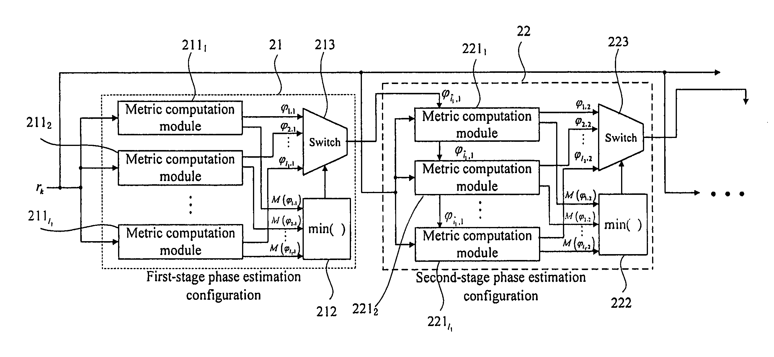
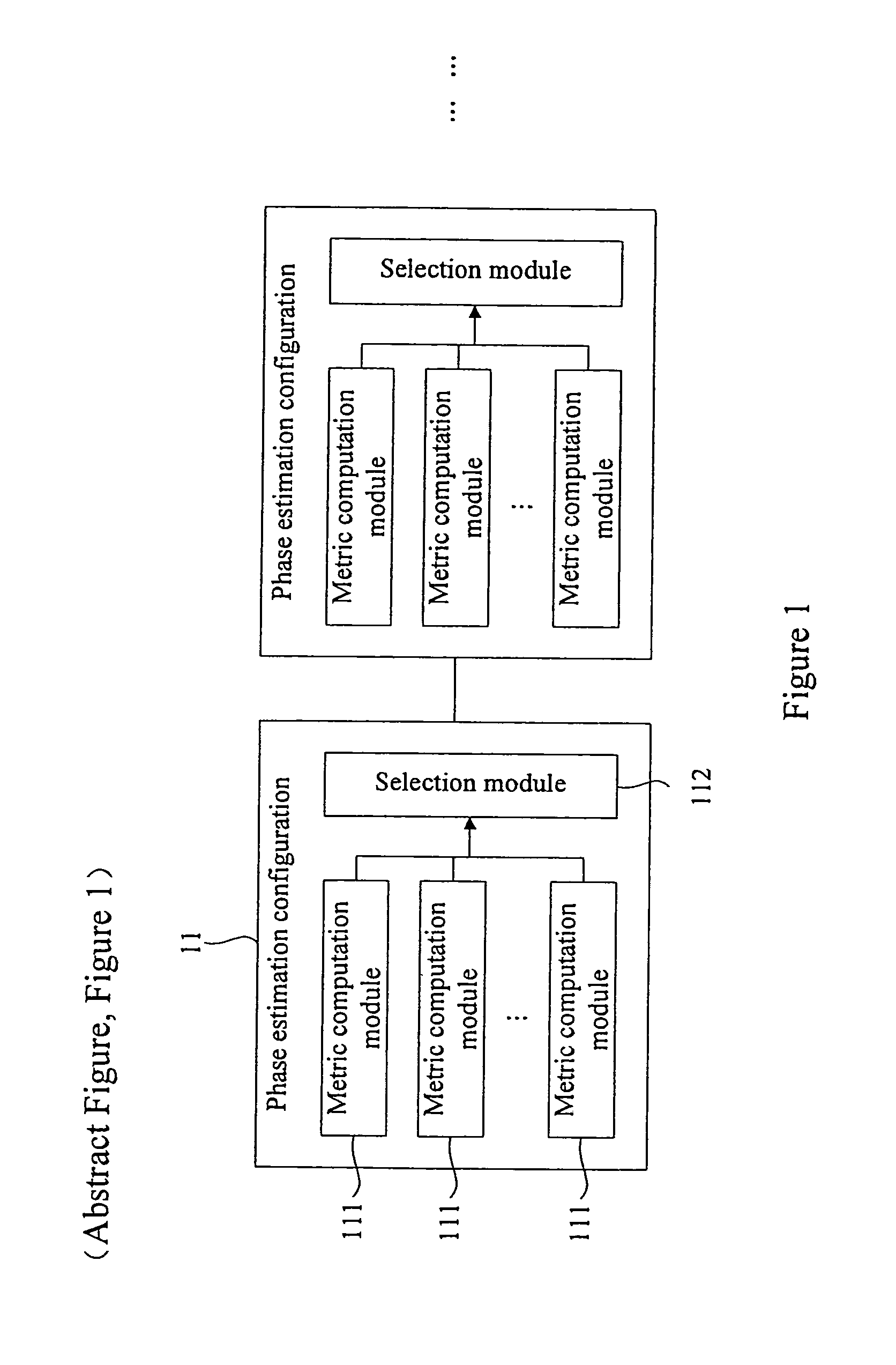
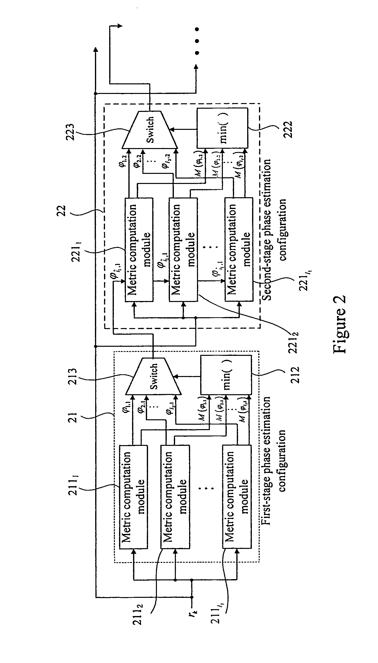
[0042]FIG. 1 is a schematic diagram of the structure of an embodiment of the multi-stage phase estimation apparatus. As shown in FIG. 1, the multi-stage phase estimation apparatus includes a multi-stage phase estimation configuration 11, each stage of the phase estimation configuration 11 including a plurality of metric computation modules 111 and a selection module 112, where the number of the metric computation modules 111 is equal to that of the search phase ang...


PUM


Abstract

The embodiments provide a multi-stage phase estimation method and apparatus. The apparatus is a multi-stage phase estimation configuration. Each stage of the phase estimation configuration includes metric computation modules. Each of the metric computation modules computing a distance metric and search phase angles according to an input signal and an initial search phase angle or a search phase angle of the former stage phase estimation configuration. The number of the metric computation modules is equal to that of the search phase angles of this stage. A selection module selects the search phase angle corresponding to the minimal distance metric as the phase estimation result output of this stage according to the computation results of all metric computation modules. The average time window length of the former stage phase estimation configuration is larger than that of the subsequent stage phase estimation configuration.

Description

CROSS REFERENCE TO RELATED APPLICATIONS[0001]This application claims the benefit of Chinese Application No. 201110093739.8, filed Apr. 14, 2011, the disclosure of which is incorporated herein by reference.TECHNICAL FIELD[0002]The embodiments relate to the field of optical communication, and in particular to a multi-stage phase estimation method and apparatus.BACKGROUND ART[0003]High-speed large-capacity optical fiber transmission systems are directions of development for future optical communications, in which high-order quadrature amplitude modulation (QAM) formats combined with coherent receiving technique provide a promising solution. On the one hand, the use of QAM formats may improve the spectral efficiency and lower the demand for the electro-optic bandwidth; and on the other hand, the coherent receiving technique may allow for overcoming the signal transmission impairments with the powerful digital signal processing (DSP) techniques while improving the receiving sensitivity.[...

Claims


Application Information

Patent Timeline
Patent Type & Authority Patents(United States)
IPC IPC(8): H04B3/46
CPCH04L27/0014
Inventor LI, JIANQIANGTAO, ZHENNINGLI, LEI
Owner FUJITSU LTD
Learn More