
Multi-antenna channel estimation method based on polyphase decomposition

a polyphase decomposition and multi-antenna channel technology, applied in the field of communication, can solve the problems of reducing the processing speed of the system, bringing a huge load on the entire communication system, etc., and achieves the effects of avoiding inversion operations, poor performance, and high complexity of the mimo channel estimation

Active Publication Date: 2014-02-18
HUAWEI TECH CO LTD
View PDF14 Cites 0 Cited by
  • Summary
  • Abstract
  • Description
  • Claims
  • Application Information

AI Technical Summary

Benefits of technology

[0044]In the MIMO channel estimation method provided in the embodiments of the present invention, the frequency domain receiving signals at the receiving end are polyphase mixed signals due to the cyclic shift characteristic of the pilot in the transmitting antenna, and polyphase decomposition and decorrelation measures are utilized to decrease the order of complexity in the implementation of the MIMO channel estimation method. In addition, the discrete cosine transformation and filtering measures are employed for the interpolation after polyphase decomposition, therefore, the MIMO channel estimation method is more accurate.

Problems solved by technology

In the existing channel estimation methods, the accurate estimation of channel parameters always involves the complex matrix operations, such as large-dimension matrix inversion; such complex matrix operations will bring huge load on the entire communication system and degrade the processing speed of the system.

Method used


Image

  • Multi-antenna channel estimation method based on polyphase decomposition
  • Multi-antenna channel estimation method based on polyphase decomposition
  • Multi-antenna channel estimation method based on polyphase decomposition

Examples


Embodiment Construction

[0048]To get a better understand of the technical schemes of the present invention, the technical schemes in the embodiments of the present invention hereunder will be described clearly and completely with the reference to the accompanying drawings. Apparently, the embodiments described below are only some embodiments of the present invention, instead of all embodiments of the present invention. Those skilled in the art can obtain other embodiments without creative work on the basis of the embodiments provided here however, all these embodiments shall be deemed as falling into the protected scope of the present invention.

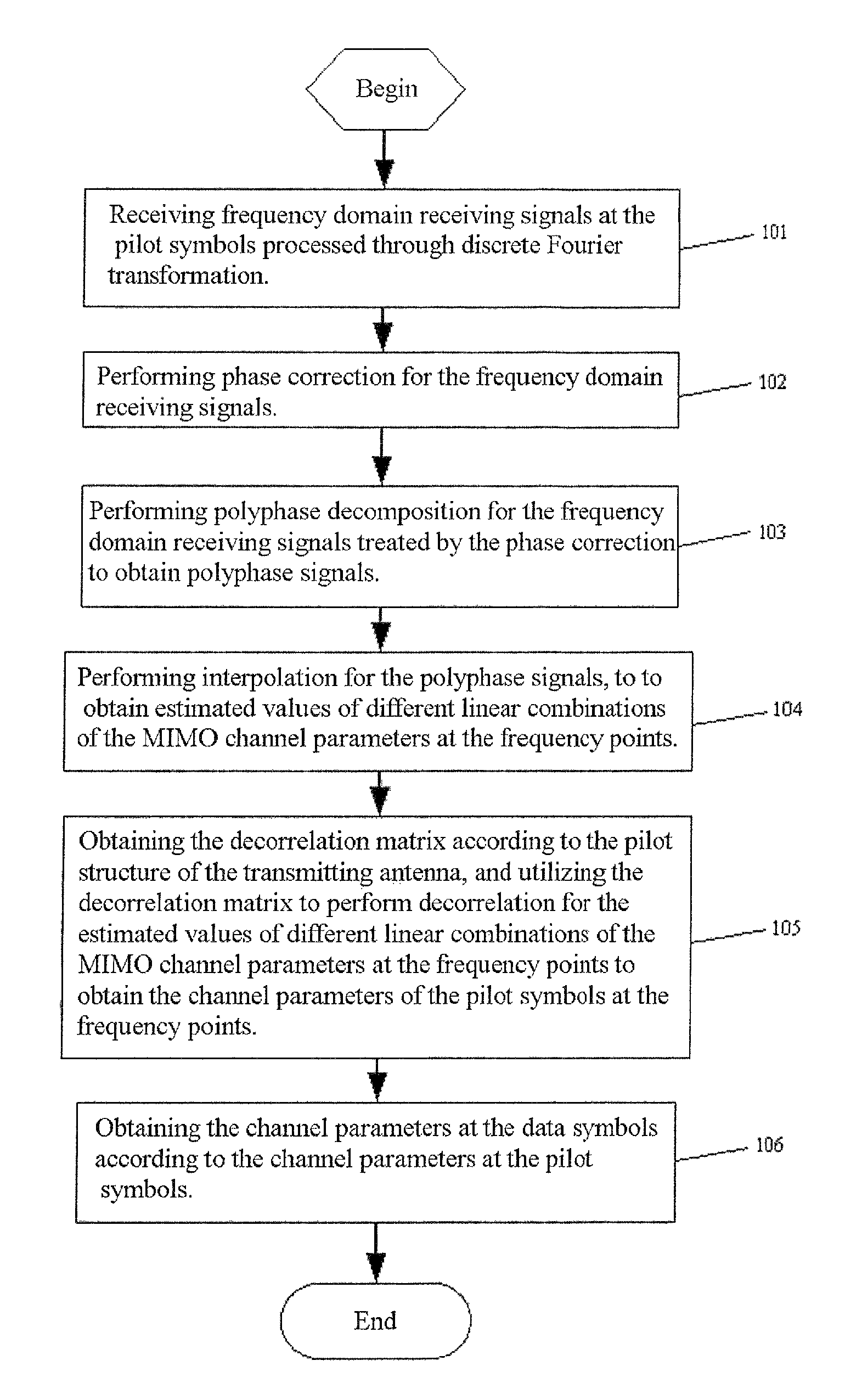
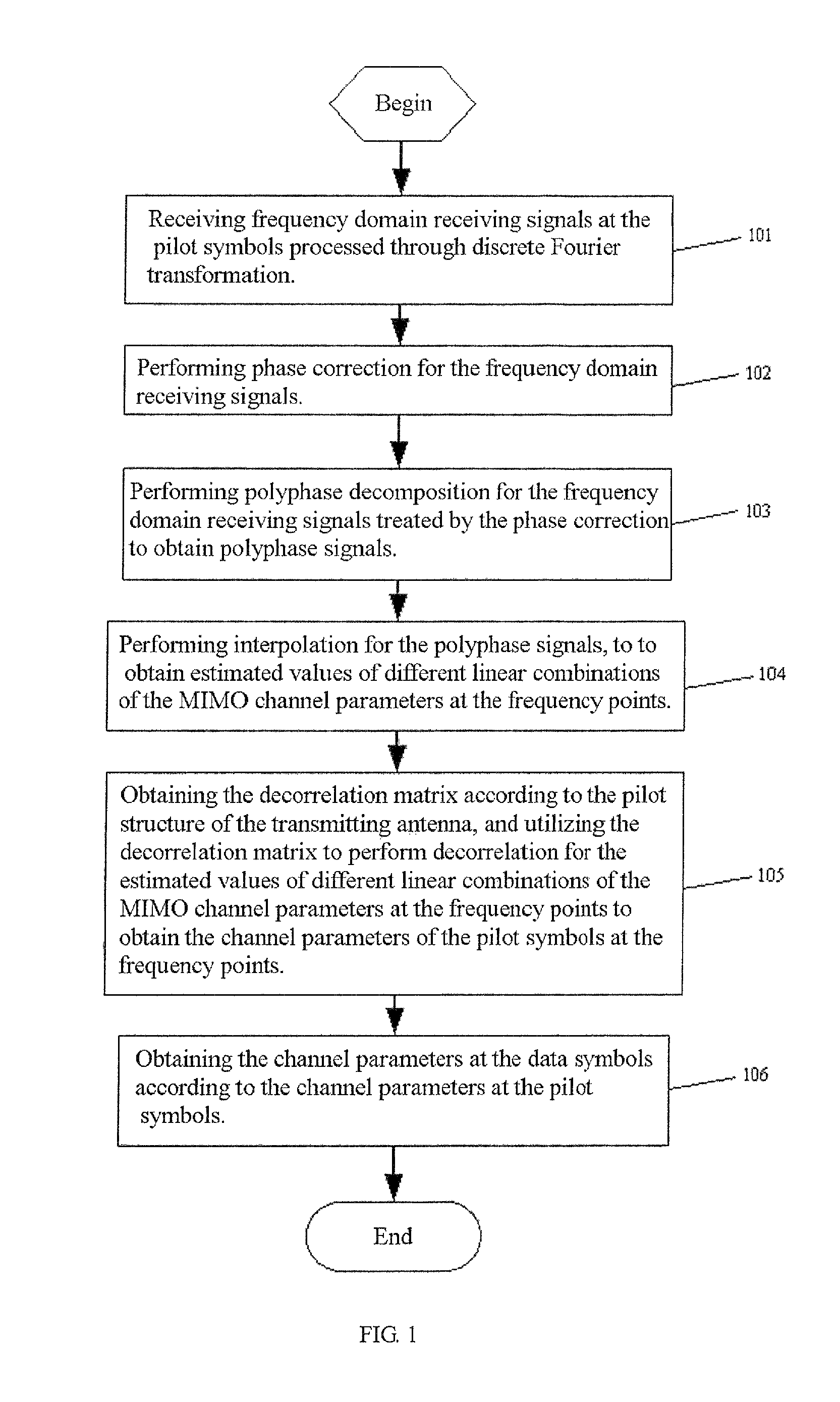
[0049]FIG. 1 shows the flow diagram of a MIMO channel estimation method provided in an embodiment of the present invention, wherein, the method comprises:

[0050]101. Receiving frequency domain receiving signals at the pilot symbols processed through discrete Fourier transformation.

[0051]In the embodiment of the present invention, the receiving signals at the pilot sy...


PUM


Abstract

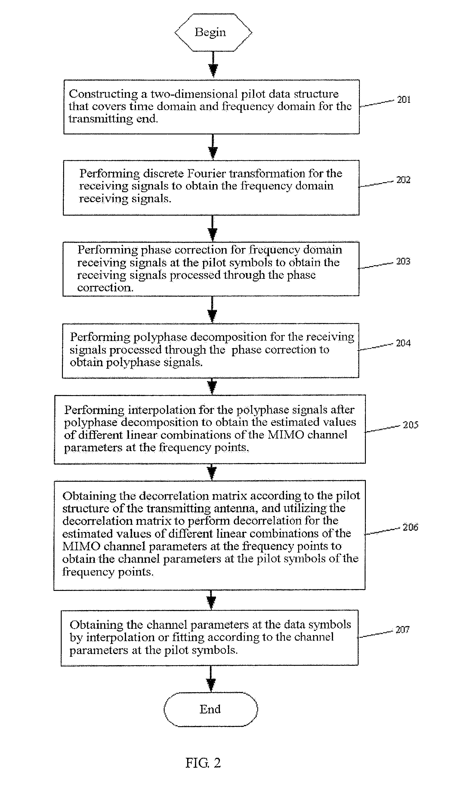
A multi-antenna channel estimation method based on polyphase decomposition includes: receiving frequency domain received signals transformed using discrete fourier transformation (DFT) in pilot symbols; performing phase correction on the frequency domain received signals; performing polyphase decomposition on the frequency domain received signals which are corrected using phase correction and acquiring polyphase signals; performing interpolation on the polyphase signals and acquiring the estimation values of the multi-antenna channel parameters with various linear combinations on each frequency; acquiring decorrelation array based on the pilot structure of the transmission antenna and decorrelating the estimation values of the multi-antenna channel parameters with various linear combination on each frequency using the decorrelation array and acquiring channel parameters of the pilot symbols on each frequency; acquiring channel parameters of data symbols based on the channel parameters of the pilot symbols. With the present invention, the inversion problem in multi-antenna channel estimation is avoided with lower complexity, and results of the multi-antenna channel estimation method become more accurate since the DFT and filtering are performed in the interpolation after polyphase decomposition.

Description

FIELD OF THE INVENTION[0001]The present invention relates to the communication field, particularly, it relates to a channel estimation method.BACKGROUND OF THE INVENTION[0002]To meet the increasing demand of future mobile communication systems for system capacity, spectrum utilization, and data transmission rate, etc., in the existing LTE (Long Term Evolution) standard, MIMO (Multiple Input Multiple Output) technique and OFDM (Orthogonal Frequency Division Multiplexing) technique are employed. Wherein, the MIMO technique can double or even triple the system capacity and spectrum utilization without increasing the bandwidth. On the other hand, the OFDM technique is a typical technique applied in wideband transmission, and it has many advantages, including high resistance to multi-path fading, insensitivity to narrow-band interference and noise, and flexible bandwidth expansion, etc.[0003]In wireless communication systems, the coherent detection technique is currently employed to achi...

Claims


Application Information

Patent Timeline
Patent Type & Authority Patents(United States)
IPC IPC(8): H04B7/02
CPCH04L25/0204H04L27/2647H04B7/0413H04L25/0232
Inventor GAO, XIQIWANG, WENJINLI, TINGZHOU, MEILIJIANG, BINZHONG, WENQIN, LONG
Owner HUAWEI TECH CO LTD
Learn More