Method for detecting a nuclear weapon in a shipping container or other vehicle using x-rays

Inactive Publication Date: 2014-02-25
MARTIN ANNIS PATENT TRUST - 2009
View PDF3 Cites 2 Cited by
  • Summary
  • Abstract
  • Description
  • Claims
  • Application Information

AI Technical Summary

Benefits of technology

The present invention is a method for improving the detection of nuclear weapons in sea cargo containers. The method involves using a system to move the container through an imaging region and detect the x-ray intensities using at least two detector columns. The detector columns have large detector elements, such as 4 cm×4 cm, and the data from each detector column is combined to create a complete image of the container. The method identifies a nuclear weapon based on the presence of a spherical core of uranium or plutonium with a mass close to the critical mass, surrounded by sufficient conventional explosive material to initiate nuclear fission or additional material that can utilize the fission bomb to initiate a fusion explosion. The method can be used with a simple hardware configuration and produces accurate results.

Problems solved by technology

Perhaps one of the most perilous threats to the United States and the western world is the possibility that a relatively small size nuclear weapon would be transported in a conventional sea cargo container into an American port and detonated there.
A rather obvious problem with respect to the inspection of a sea cargo container that might have a nuclear weapon inside is that the weapon could even be detonated while the container ship was in the harbor.
However as long as 30 years ago, the U.S. Customs Service found that even a substantial quantity of uranium or plutonium in the center of a fully loaded container could not be detected using passive detectors because of the absorption of the emitted gamma radiation by the typical contents.
First, they are, at best, hopelessly expensive in a full scale deployment.
Second, they are still ten years away from a successful prototype and the threat is more immediate.
The evaluation of the two images is quite difficult since it is extremely hard to identify the same object in the two images.
Another difficulty is that, even using the highest available peak x-ray sources, the effective penetration of the contents is less than 2′ of iron in a typical sea cargo container that is 8′×12′×40′ long.

Method used


Image

  • Method for detecting a nuclear weapon in a shipping container or other vehicle using x-rays
  • Method for detecting a nuclear weapon in a shipping container or other vehicle using x-rays
  • Method for detecting a nuclear weapon in a shipping container or other vehicle using x-rays

Examples


Embodiment Construction

[0028]The present specification describes two inventions. The first is an apparatus and method for using lower power x-ray sources for inspecting sea cargo containers and other transportation vehicles. The second invention is a method of substantially improving the current state of the art in x-ray inspection of sea cargo containers, particularly in the detection of nuclear weapons.

[0029]Using Lower Power X-Ray Sources

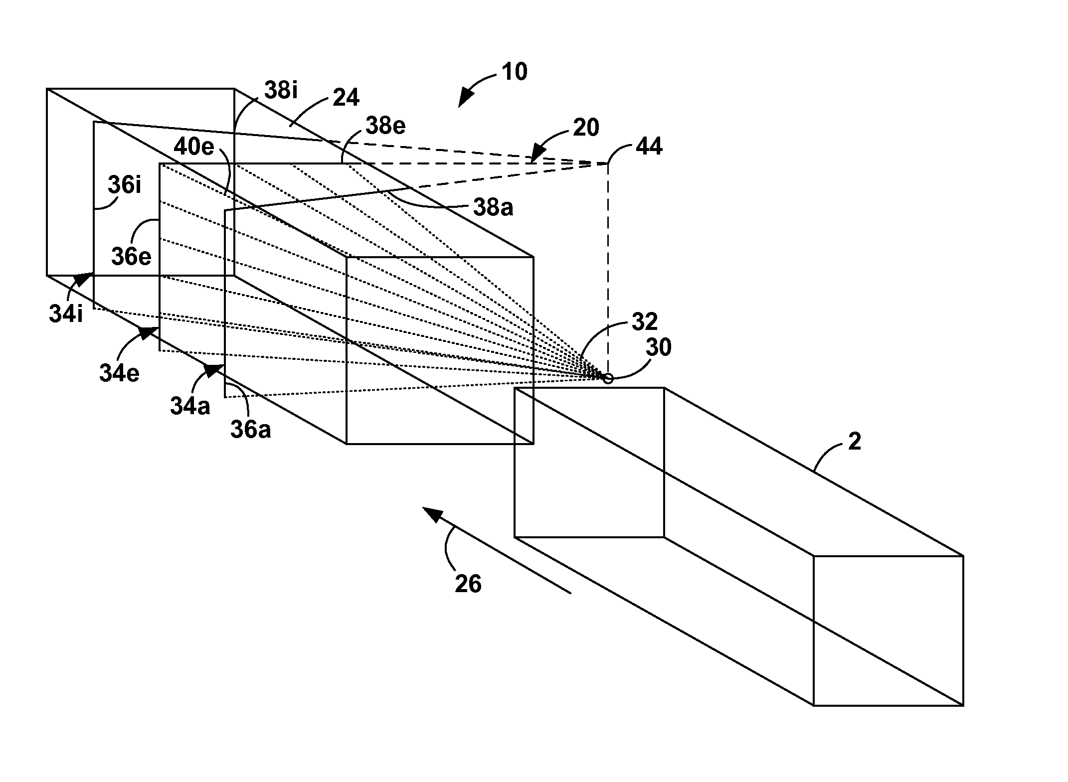
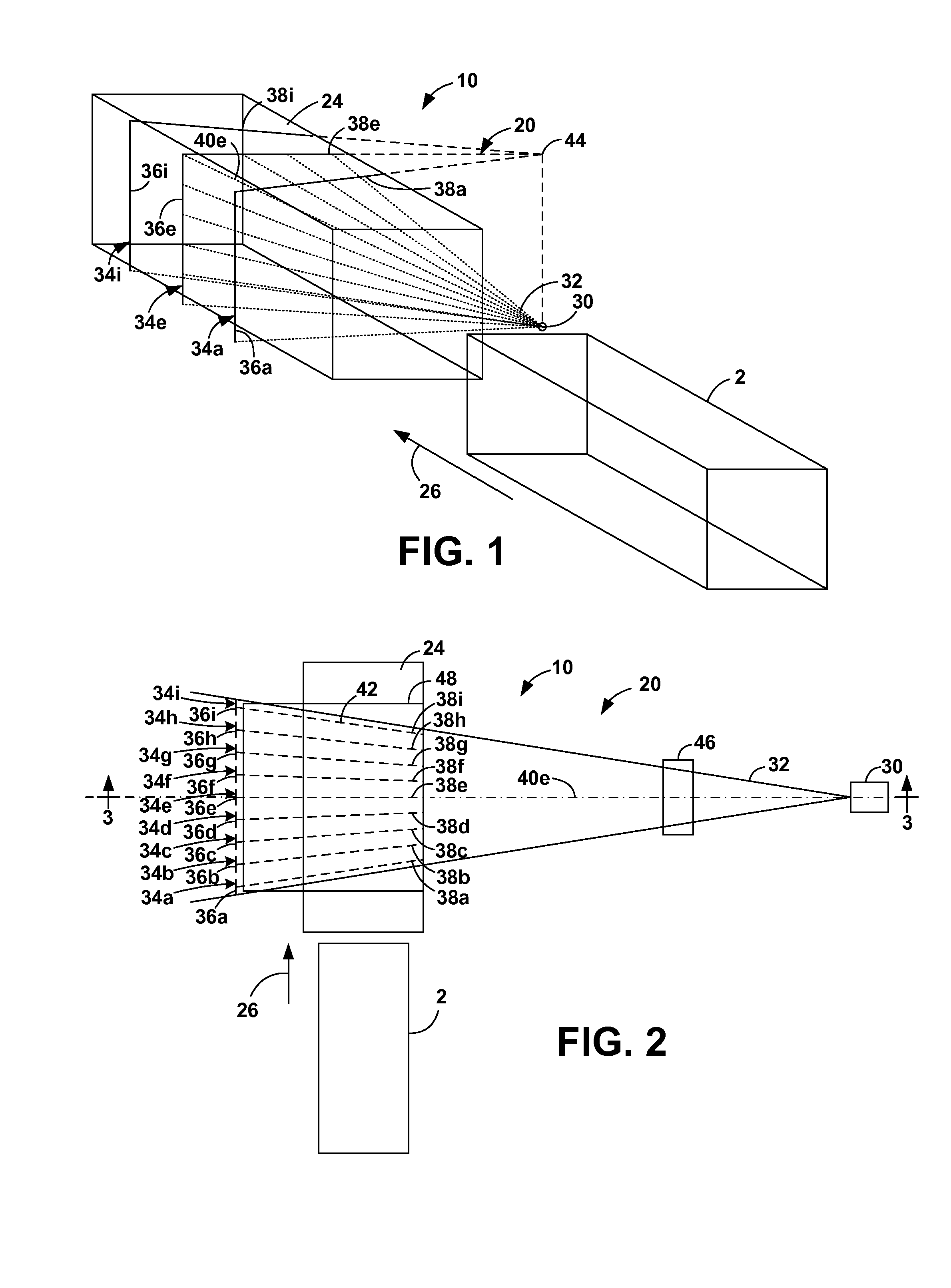
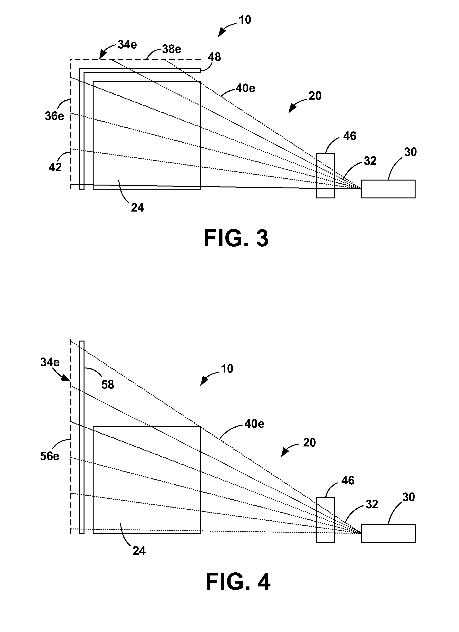
[0030]A system 10 to inspect sea cargo containers is shown in FIGS. 1-4. The object 2 moves in a longitudinal direction of motion 26 through an imaging region 24. A 6 MeV x-ray source 30 emits a cone beam 32 into the imaging region 24 from outside of the imaging region 24. A plurality of x-ray detector assemblies 34a-i (collectively, 34) are located outside the imaging region 24 opposite the x-ray source 30. Each detector assembly 34 includes a plurality of relatively large detector elements 42 and defines an x-ray fan beam 40a-i (collectively, 40) within the imaging r...


PUM


Abstract

A method of improving the detection of nuclear weapons in cargo containers. The container moves through an imaging region. An x-ray source emits a cone beam through the imaging region and to two or more detector columns, each detector column defining a fan beam. This hardware combines (1) the use of at least two detector assemblies, (2) use of both the current method and the photon counting method to determine x-ray intensities, and (3) use of large detector elements to increase the measured x-ray intensity by a typical factor of 270. The x-ray intensity for a pixel is read by each detector assembly at the appropriate time and the resulting x-ray intensities from each detector assembly are summed. A method of detecting a nuclear weapon includes identifying the nuclear device as the area of the image wherein a high absorption area is surrounded by a lower absorption area.

Description

CROSS-REFERENCES TO RELATED APPLICATIONS[0001]The present application is a continuation-in-part application of application Ser. No. 13 / 153,732, filed Jun. 6, 2011 for METHOD FOR DETECTING A NUCLEAR WEAPON IN A SHIPPING CONTAINER OR OTHER VEHICLE USING X-RAYS in the name of Martin Annis, hereby incorporated by reference in its entirety, which claims the benefit of and priority to U.S. Provisional Patent Application No. 61 / 396,864, filed on Jun. 4, 2010 for title METHOD TO DETECT A NUCLEAR WEAPON IN A SEA CARGO CONTAINER OR OTHER VEHICLE USING X-RADIATION in the name of Martin Annis, hereby incorporated by reference in its entirety.STATEMENT REGARDING FEDERALLY SPONSORED RESEARCH OR DEVELOPMENT[0002]Not ApplicableREFERENCE TO A SEQUENCE LISTING, A TABLE, OR A COMPUTER PROGRAM LISTING COMPACT DISK APPENDIX[0003]Not ApplicableBACKGROUND OF THE INVENTION[0004]1. Field of the Invention[0005]The present invention relates to weapons detection, more particularly, to detecting nuclear weapons...

Claims


Application Information

Patent Timeline
IPC IPC(8): G01N23/04
CPCG01V5/0091G01V5/281
Inventor ANNIS, MARTIN
Owner MARTIN ANNIS PATENT TRUST - 2009
Why Eureka
Try Eureka