Pressure sensor

a technology of pressure sensor and pressure sensor, which is applied in the direction of fluid pressure measurement, variable capacitor, instruments, etc., can solve the problems of insufficient elimination of thermal deformation effect, difficult to accurately measure pressure, and frequency chang

Inactive Publication Date: 2014-03-11
SEIKO EPSON CORP
View PDF43 Cites 8 Cited by
  • Summary
  • Abstract
  • Description
  • Claims
  • Application Information

AI Technical Summary

Benefits of technology

[0017]With this configuration, since the base portions at both ends of the pressure sensitive element are, as a result, connected to the side of the pressure receiving member, it is possible to suppress thermal deformation of the pressure sensitive element resulting from expansion and contraction due to an overall change in temperature of the container. On the other hand, thermal deformation occurs between the frame and the pressure receiving member. However, since the amount of expansion and contraction of the shock absorbing portion that constitutes the frame is larger than the amount of expansion and contraction of the pressure sensitive element in response to this thermal stress, the shock absorbing portion receives most of the thermal deformation applied to the frame. Thus, the pressure sensor is capable of decreasing the thermal deformation applied to the pressure sensitive element and suppressing pressure errors due to a change in temperature. Moreover, the frame can be connected to the side of the container close to the pressure receiving member. With this configuration, since the frame is connected to the container having high rigidity, it is possible to increase the pressure sensitivity of the pressure sensitive element.Application Example 2
[0022]With this configuration, it is possible to decrease the thermal deformation between the frame and the pressure sensitive element. Moreover, since the frame and the pressure sensitive element are integrally formed, it is possible to decrease the number of components and realize cost reduction.Application Example 4
[0026]With this configuration, it is possible to decrease the thermal deformation between the pressure sensitive element and the shock absorbing portion.Application Example 6
[0036]With this configuration, since two pressure receiving members are formed in one housing, a pressure sensor in which the pressure sensitive element and the frame are provided so as to correspond to each pressure receiving member can be obtained. In this case, since two pressure sensitive elements are located within the same housing, it is possible to obtain a pressure sensor which can measure a pressure difference between the different amounts of pressure applied to the respective pressure receiving members accurately.

Problems solved by technology

As a result, the resonance frequency changes, and it is difficult to measure pressure accurately.
Thus, it is not possible to sufficiently eliminate the effect of thermal deformation.
On the other hand, thermal deformation occurs between the frame and the pressure receiving member.
However, since the amount of expansion and contraction of the shock absorbing portion that constitutes the frame is larger than the amount of expansion and contraction of the pressure sensitive element in response to this thermal stress, the shock absorbing portion receives most of the thermal deformation applied to the frame.

Method used


Image

  • Pressure sensor
  • Pressure sensor
  • Pressure sensor

Examples


first embodiment

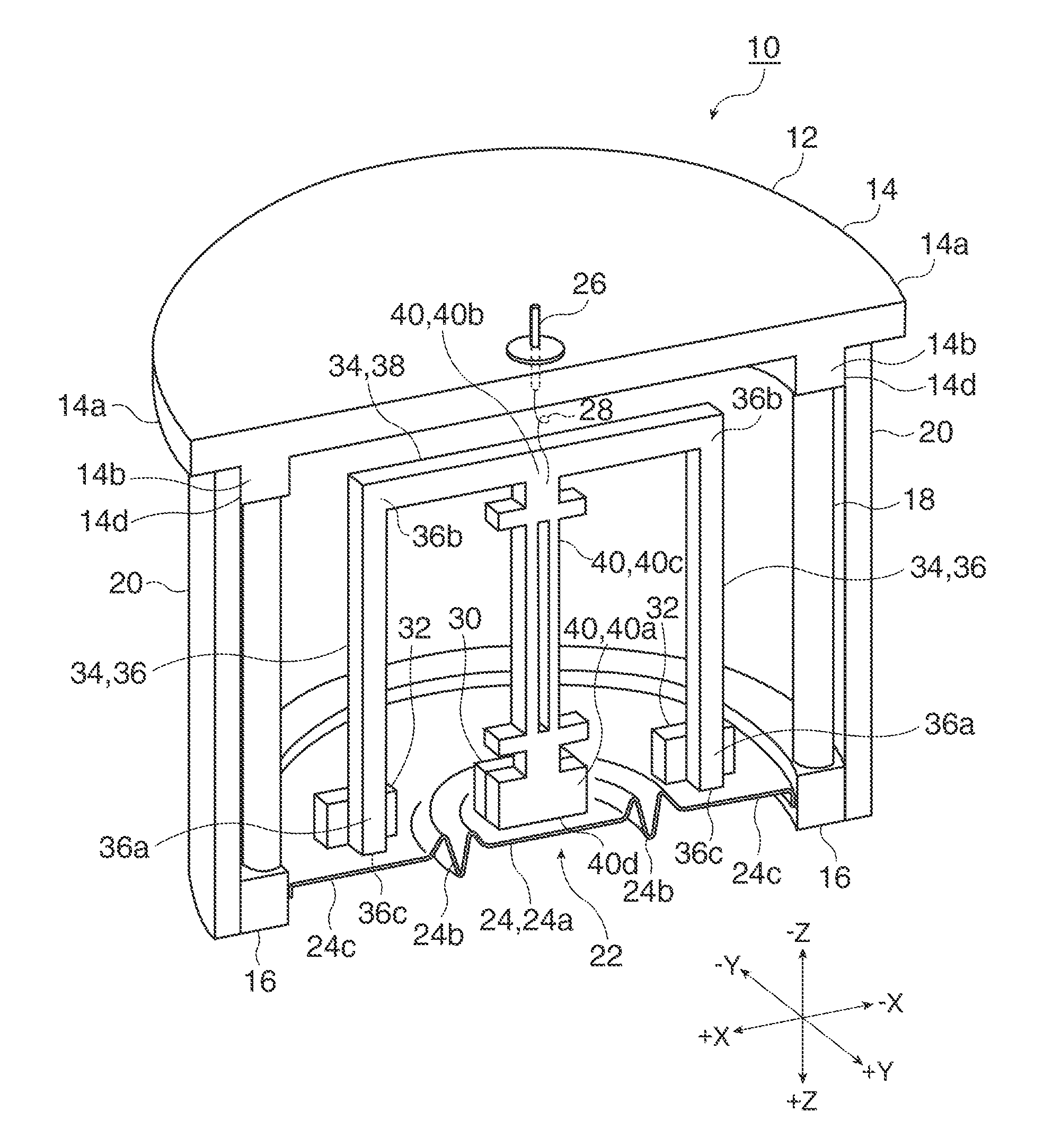
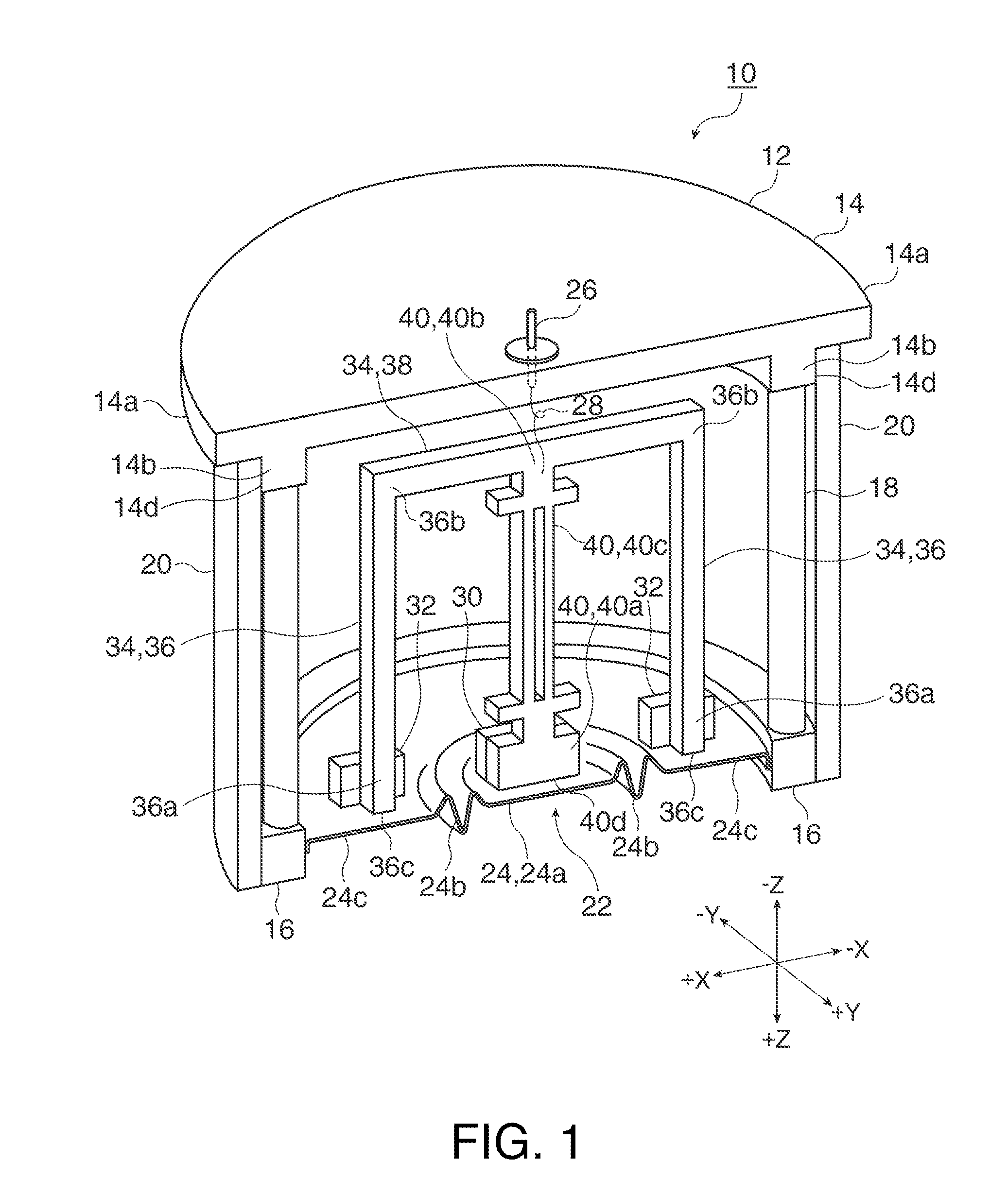
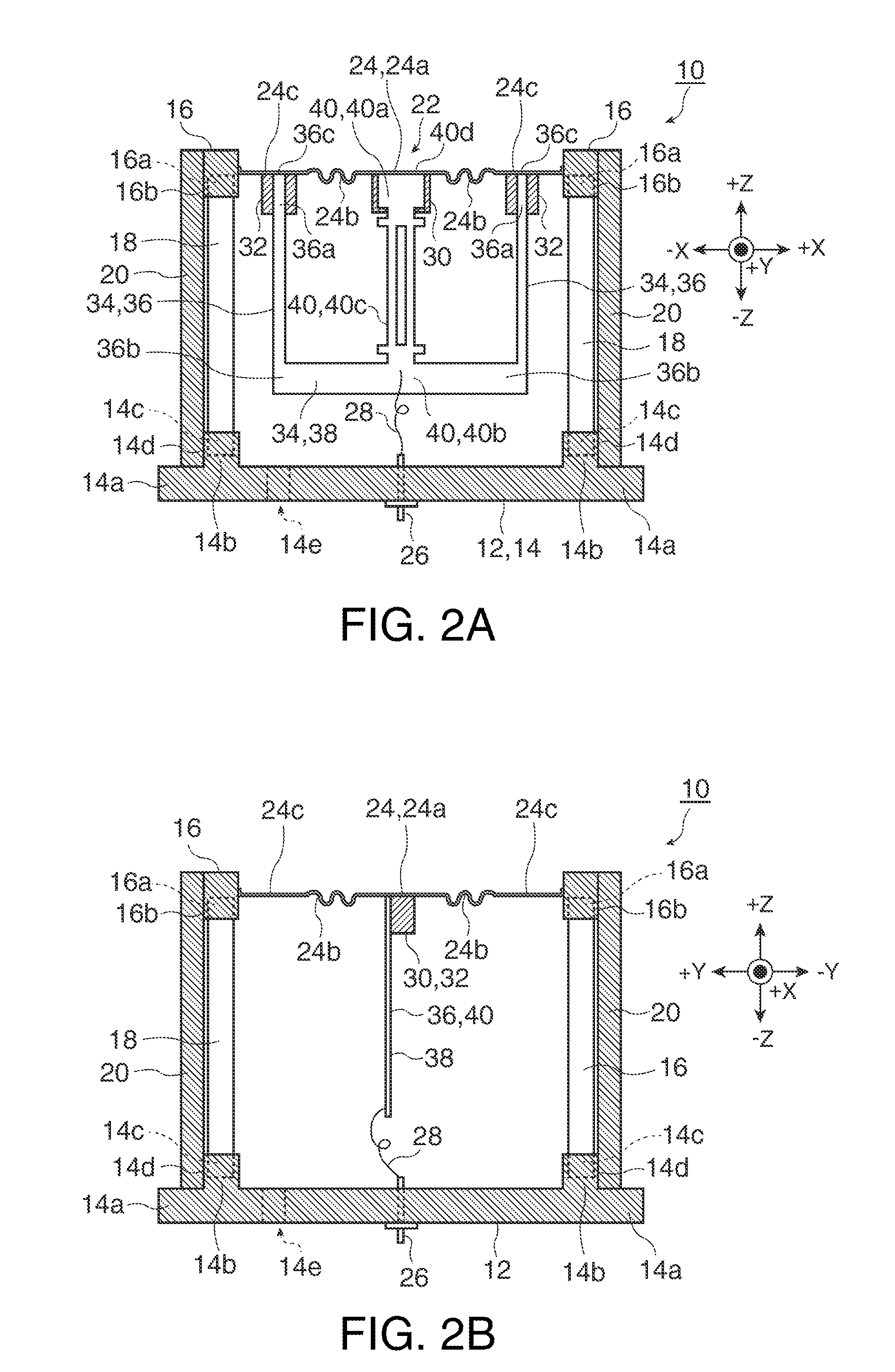
[0054]FIG. 1 is a perspective cross-sectional view of a pressure sensor according to a first embodiment, taken along the XZ plane. FIGS. 2A and 2B are cross-sectional views of the pressure sensor according to the first embodiment, taken along the XZ and YZ planes, respectively. Here, the X, Y, and Z axes shown in FIGS. 1, 2A, and 2B constitute an orthogonal coordinate system, and the same is applied to the drawings referred to hereinafter. A pressure sensor 10 according to the first embodiment includes a housing 12 and a diaphragm 24 which serve as a container. A shock absorbing portion 36 and a beam portion 38 which constitute a frame 34, a pressure sensitive element 40, and the like are accommodated in the accommodation space of the container having the diaphragm 24. Moreover, when the inside of the housing 12 is opened to the atmosphere, for example, the pressure sensor 10 can be used as a fluid pressure sensor that receives fluid pressure from outside the diaphragm 24 with refer...

second embodiment

[0101]A pressure sensor according to a second embodiment is shown in FIGS. 6, 7A, and 7B. FIG. 6 is a perspective cross-sectional view of the pressure sensor according to the second embodiment, taken along the XZ plane. FIGS. 7A and 7B are cross-sectional views of the pressure sensor according to the second embodiment, taken along the XZ and YZ planes, respectively.

[0102]A pressure sensor 50 according to the second embodiment is basically similar to that of the first embodiment, but is different in that the frame (a shock absorbing portion 52 and a beam portion 54) and a pressure sensitive element 56 are separately formed and are connected by an adhesive agent or the like. In the following description, the same constituent elements as those of the first embodiment will be denoted by the same reference numerals, and detailed description thereof will be omitted unless necessary.

[0103]In the second embodiment, the beam portion 54 is formed of a material having the same thermal expansio...

third embodiment

[0107]FIGS. 10A and 10B show cross-sectional views of a pressure sensor according to a third embodiment, taken along the XZ and YZ planes, respectively. The pressure sensor 70 according to the third embodiment is basically similar to that of the first and second embodiments but is different in that the shock absorbing portion 36 is connected to the side of a diaphragm 86 of a housing 72. Although the present embodiment will be described by way of the frame 34 and the pressure sensitive element 40 used in the first embodiment, the present embodiment can be applied to the shock absorbing portion 52, the beam portion 54, and the pressure sensitive element 56 of the second embodiment. Moreover, the present embodiment is used when the rigidity of the peripheral portion of the diaphragm 24 of the first embodiment is not sufficient for pressure from the outside. That is, in the present embodiment, since the shock absorbing portion 36 (52) is connected to a housing having high rigidity as d...


PUM

PropertyMeasurementUnit
forceaaaaaaaaaa
pressureaaaaaaaaaa
lengthaaaaaaaaaa

Abstract

A pressure sensor includes: a container; a pressure receiving member which forms apart of the container; a pressure sensitive element which has a pressure sensing portion and a pair of base portions connected to both ends of the pressure sensing portion, and which has a detection axis parallel to a line connecting the base portions, and in which the detection axis is parallel to a displacement direction of the pressure receiving member, and which detects pressure based on displacement of the pressure receiving member; and a gate-shaped frame which includes a pair of shock absorbing portions that interposes the pressure sensitive element and is connected to a side of the pressure receiving member close to the peripheral portion or a side of the container close to the pressure receiving member and a beam portion that connects distal ends of the shock absorbing portions.

Description

BACKGROUND[0001]1. Technical Field[0002]The present invention relates to a pressure sensor, and more particularly to a pressure sensor capable of suppressing measurement errors due to a change in temperature.[0003]2. Related Art[0004]In the related art, pressure sensors which use a piezoelectric vibrating element as a pressure sensitive element are known such as a hydraulic pressure meter, a barometer, a differential pressure meter, and the like. In a pressure sensor using a piezoelectric vibrating element, when pressure is applied to the piezoelectric vibrating element in the detection axis direction thereof, the resonance frequency of the piezoelectric vibrating element changes, and pressure applied to the pressure sensor is detected from a change in the resonance frequency.[0005]JP-A-2007-57395, JP-A-2005-121628, and JP-A-2010-25582 disclose pressure sensors that use a piezoelectric vibrator as a pressure sensitive element. FIG. 13 shows a pressure sensor disclosed in JP-A-2007-5...

Claims


Application Information

Patent Timeline
Patent Type & Authority Patents(United States)
IPC IPC(8): G01L9/00
CPCG01L9/008
Inventor SATO, KENTA
Owner SEIKO EPSON CORP
Why Eureka
Try Eureka