Aero-acoustic optimisation method for complex-section mechanical parts and corresponding mechanical part and landing gear

a technology of mechanical parts and optimisation methods, applied in the direction of airflow influencers, applications, instruments, etc., can solve the problems of surface noise generation, disturbance of airflow, parasite drag, etc., and achieve the effect of simple tools and easy operation

Active Publication Date: 2014-03-11
AIRBUS OPERATIONS (SAS)
View PDF13 Cites 9 Cited by
  • Summary
  • Abstract
  • Description
  • Claims
  • Application Information

AI Technical Summary

Benefits of technology

[0011]This invention is intended to reduce the drag and aerodynamic noise of a structural part, for example of the landing gear of an aircraft, making it possible to optimize the lift / drag ratio, by reducing the local noise source, which causes aerodynamic disturbances attributable to the complex section of the part, combined with an overall optimization of the aircraft related to the reduction in drag. Such a combination makes it possible to optimize the thrust of the engine in the case of an aircraft, without modifying the mechanical properties of the part or interfering with inspections of parts, in particular parts of a landing gear, or compromising the gear retraction function. To do so, the invention provides for the aerodynamic shaping of the complex part by masking its form with a special casing.
[0015]Advantageously, the supports enable the cover to be held without rotating or moving along the part, in particular by incorporating stops. Furthermore, the cover-support assembly leaves some clearance between the part and the supports, obviating any risk of moisture accumulation or damage to the part. The cover, which is separate from the part, is therefore not subject to the potential deformations of this part.
[0023]Advantageously, the supports and the cover of each strut are modelled sufficiently closely to the “H” shaped section such as to ensure that retraction of the gear into the hold is not impeded and that there is no interaction with other parts. Furthermore, the installation and removal of the supports and the cover, for example for an inspection or a retrofit, are easily undertaken with simple tools and require no specific fixing point on the landing gear, such that their presence does not disturb inspections of the landing gear.

Problems solved by technology

However, these structures cause the appearance of disturbances in an airflow.
Effectively, if such a part is placed in an airflow, pressure fluctuations caused by the marked geometric variations in the surface of the part cause the appearance of vortexes forming a parasite drag.
The interaction between such a turbulent flow and the solid surfaces of the part then generate an aerodynamic noise.
Indeed, during this phase, the landing gear is lowered long before landing, for safety reasons, which causes the appearance of a highly turbulent flow and an aerodynamic noise.
Moreover, during approach and take-off phases, the aircraft requires an optimum lift / drag ratio to best negotiate the flying conditions, speed being particularly low in these phases.
Furthermore, on take-off, an excess of drag requires an increase in thrust.
However, this solution may increase the mass of the landing gear.
Moreover, if complex-section parts are replaced with bars, their mechanical properties can only be retained by increasing the size of the parts, and therefore the space they occupy.
However, such an approach conflicts with maintenance conditions and complicates maintenance work.
Indeed, such coatings require the removal of the structural part, prevent certain elements of the landing gear from being checked as the part is obscured, and need to be changed frequently on account of their usage conditions, resulting in additional grounding of the aircraft.

Method used


Image

  • Aero-acoustic optimisation method for complex-section mechanical parts and corresponding mechanical part and landing gear
  • Aero-acoustic optimisation method for complex-section mechanical parts and corresponding mechanical part and landing gear
  • Aero-acoustic optimisation method for complex-section mechanical parts and corresponding mechanical part and landing gear

Examples


Embodiment Construction

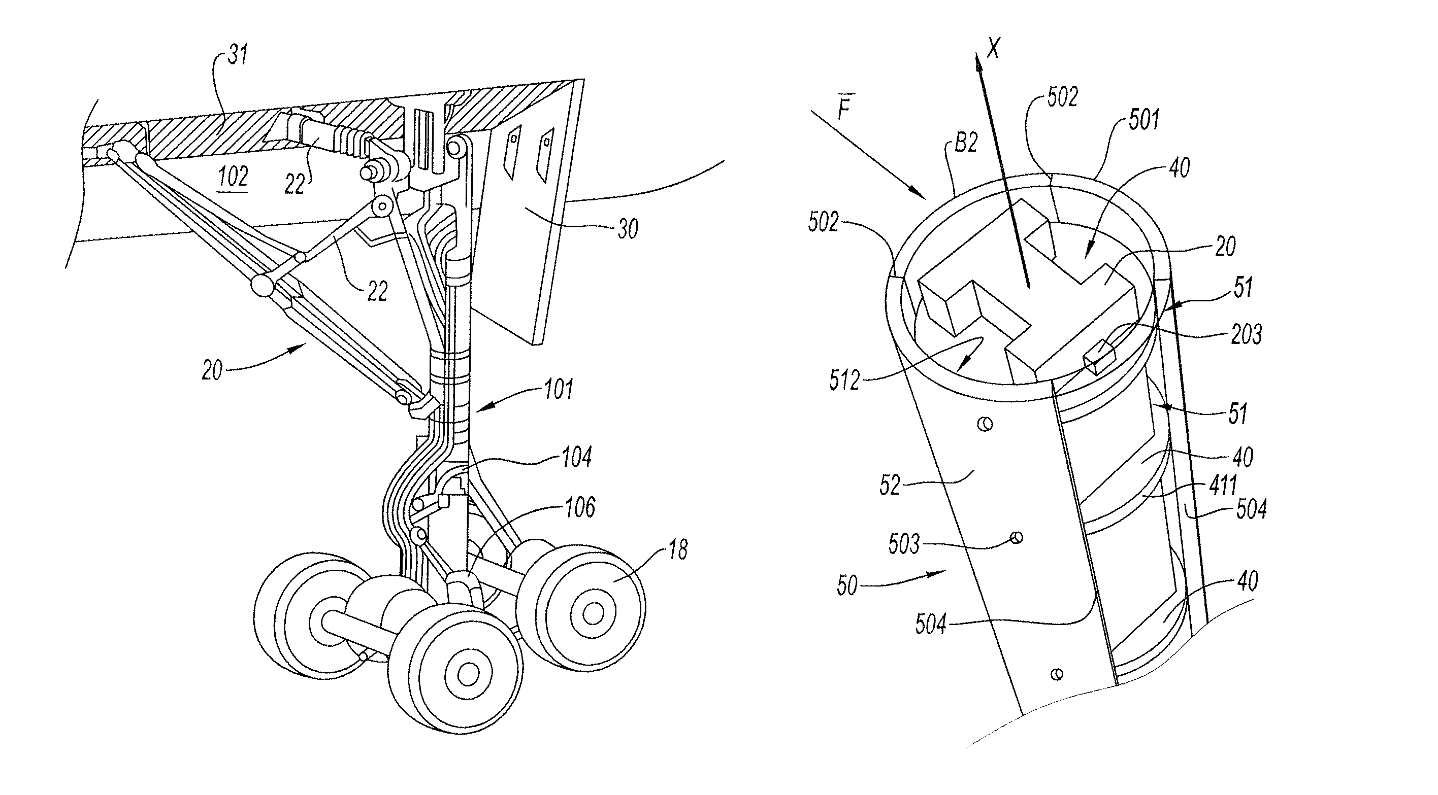
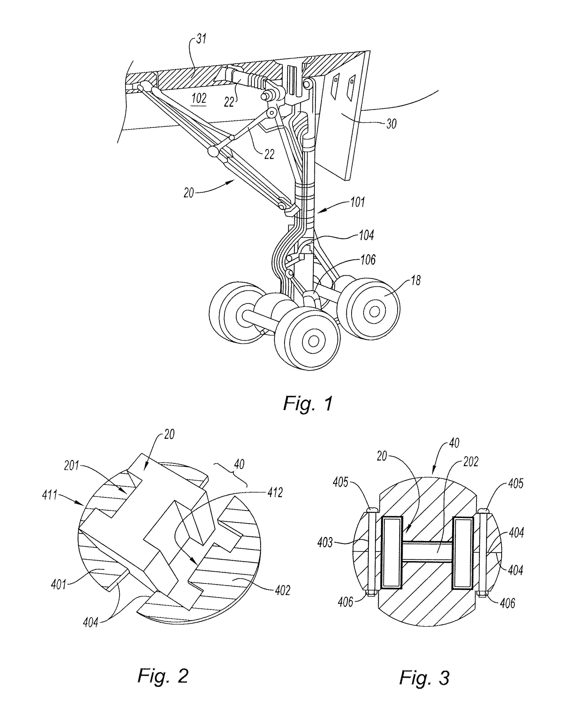
[0030]With reference to FIG. 1, a landing gear on the ground comprises schematically a main shaft 101, connected to an aircraft structure 102, to which are connected a shock absorber 104 and a positioning cylinder 106 and, at the end, pairs of wheels 18. A main strut 20 and a secondary strut 22 brace the articulation of the main shaft 101 in the aircraft structure 102 through the hatch 30 in the hold 31 which is open when idle, as shown in the figure.

[0031]The parts and in particular the struts 20, 22 are made of metal alloy. The struts 20, 22, as shown schematically by strut 20 in FIG. 2, have an “H” section longitudinal part structure, with wide deep longitudinal grooves 201. This shape provides parts with particularly high mechanical torsional strength and rigidity properties.

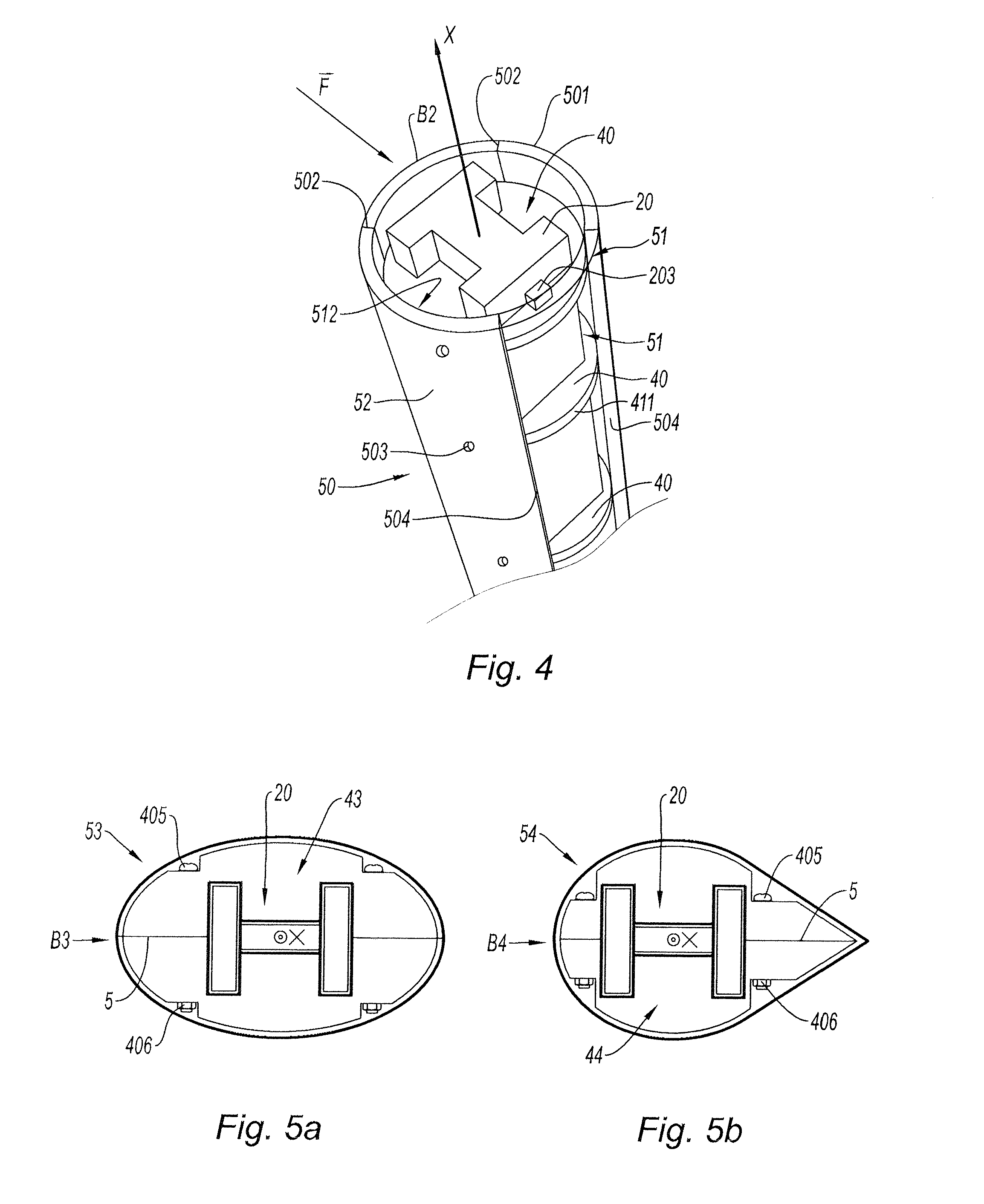
[0032]In order to significantly reduce the parasite drag and the noise caused by the presence of these struts 20 when the landing gear 10 is deployed from the hold, such parts are provided with an envelope f...


PUM

PropertyMeasurementUnit
passive noise absorptionaaaaaaaaaa
mechanicalaaaaaaaaaa
thicknessaaaaaaaaaa

Abstract

An apparatus and method are provided for reducing the drag caused by a complex-section part in an airflow, for example the landing gear of an aircraft, making it possible to optimize the lift / drag ratio and to reduce the aerodynamic noise by reducing the local noise source. To do so, the complex-section part is masked with a special casing. More specifically, the aero-acoustically optimized complex-section metal mechanical part is fitted with an aerodynamically shaped cover made of several longitudinal parts articulated with hinges to facilitate their installation. This cover is attached to at least two supports placed away from one another along the axis of the part, each support locally mating with the section of the part.

Description

CROSS-REFERENCE TO RELATED APPLICATION[0001]This application claims priority to French Application No. 10 54911, filed on Jun. 21, 2010.TECHNICAL FIELD[0002]The invention relates to an aero-acoustic optimization method for complex-section mechanical parts, a mechanical part of this type, in particular “H” shaped, produced using this method and the landing gear of an aircraft comprising at least one such mechanical part as a strut.BACKGROUND[0003]Complex section or shape structures—i.e. structures with deep longitudinal grooves and, for example, an “H” or “X” section—have enhanced mechanical yield strength and rigidity properties. However, these structures cause the appearance of disturbances in an airflow. Effectively, if such a part is placed in an airflow, pressure fluctuations caused by the marked geometric variations in the surface of the part cause the appearance of vortexes forming a parasite drag. The interaction between such a turbulent flow and the solid surfaces of the par...

Claims


Application Information

Patent Timeline
Patent Type & Authority Patents(United States)
IPC IPC(8): B64C25/16
CPCB64C7/00B64C2025/003B64C25/16B64C25/001Y10T29/49Y10T428/12361Y10T428/12375
Inventor SEROR, GOGUET, CHRISTELLE
Owner AIRBUS OPERATIONS (SAS)
Why Eureka
Try Eureka