Cooling of the tip of a blade

Active Publication Date: 2014-03-18
SN DETUDE & DE CONSTR DE MOTEURS DAVIATION S N E C M A
View PDF25 Cites 15 Cited by
  • Summary
  • Abstract
  • Description
  • Claims
  • Application Information

AI Technical Summary

Benefits of technology

The invention improves cooling for the blade tip, specifically the upper part of the blade, near the tungsten blade trailing edge. This helps to prevent damage to the blade and improve its overall performance.

Problems solved by technology

Moreover, they make it possible to limit the passage of gas from the upper surface toward the lower surface generating aerodynamic losses that are detrimental to the yield.
However, the solution proposed by this document does not allow sufficient cooling of several zones of the cavity.
Indeed, the gradient of the temperatures T of the gases in the vicinity of the blade depending on the height H of the vein of the gases (FIG. 3) is particularly damaging for several zones of the cavity.

Method used


Image

  • Cooling of the tip of a blade
  • Cooling of the tip of a blade
  • Cooling of the tip of a blade

Examples


first embodiment

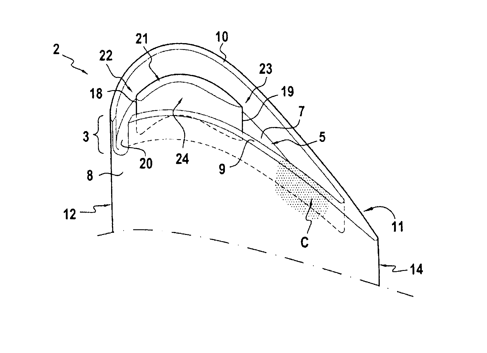
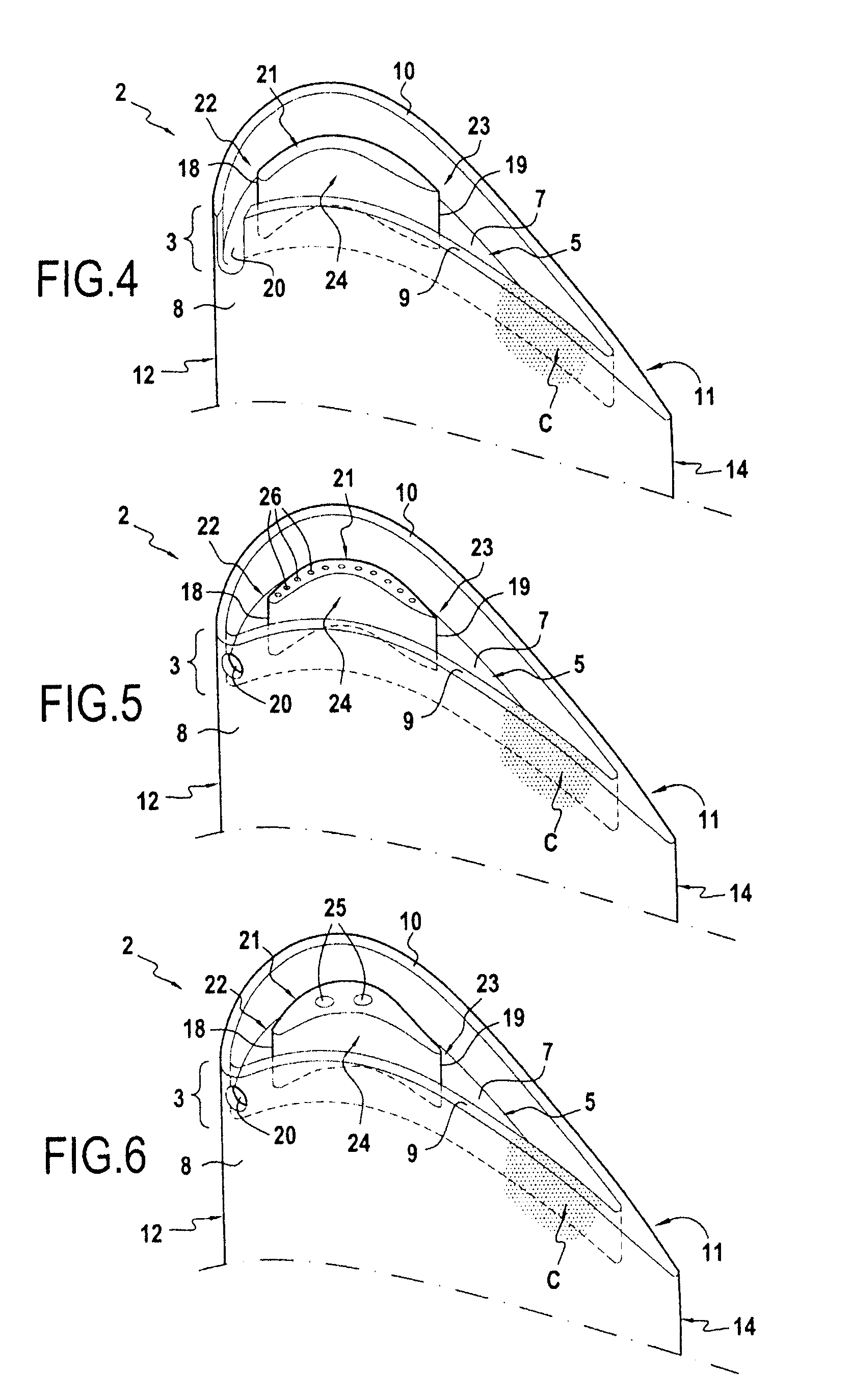
[0018]the invention is described in reference to FIG. 4. In this embodiment, the opening 20 of the side wall 9, 10 of the cavity 5 is situated in the vicinity of the leading edge 12 of the blade 2, on the lower surface side 8. Without being restrictive, this opening position 20 makes it possible to withdraw the cooling gases (i.e. essentially less hot) in the outer portion of the vein of the gases particularly effectively. Of course, depending on the geometry of the blade and the angle of incidence of the gases, the opening 20 may be placed further downstream on the lower rim 9 or on the other side on the upper rim 10.

[0019]In this example, the opening 20 of the side wall 9, 10 of the cavity 5 is a recess. The height of this recess can vary according to different embodiments. Here, the recess extends over the entire height of the side wall 9, 10 of the cavity 5. This recess height has the advantage, for a given width, of providing the cavity with a maximum gas flow.

[0020]In this fir...

second embodiment

[0024]the invention is described in reference to FIG. 5. In this example, the opening 20 of the side wall 9, 10 of the cavity 5 is a hole. The cylindrical shape of the hole illustrated in this example is not limiting. The hole can have an oblong or triangular shape, among others. As side wall opening of the cavity 5, the hole has the advantage of being able to precisely adjust the flow of cooling gas entering the cavity 5.

[0025]This second example illustrates a hollow blade 2 supplied with cooling gas, and the deflector 21 includes cooling holes 26 communicating with at least one hollow portion of the blade. These cooling holes are radial bores in the deflector 21. They open into an inner cavity of the blade 2 situated under the deflector 21. The cooling of the deflector 21 is thus ensured by pumping and heat conduction. Moreover, the cooling of the deflector 21 makes it possible to lower, by convection, the temperature of the gases deviated by the latter, consequently increasing th...

third embodiment

[0026]the invention is described in reference to FIG. 6. This third example shows a hollow blade 2 supplied with cooling gas, and the deflector 21 includes dust extraction holes 25 communicating with at least one hollow portion of the blade. These dust extraction holes are similar to the cooling holes and ensure, like the latter, the cooling of the cavity 5. However, they have a larger diameter than that of the traditional cooling holes. The larger diameter of the dust extraction holes allows the evacuation of dust that may be present in the inner cavity(ies) of the blade. Thus, on a deflector having both types of holes, the dust will preferably pass through the dust extraction holes rather than through the narrower cooling holes. One therefore avoids covering the cooling holes of small diameter.

[0027]Because of the significant diameter of these dust extraction holes, it is necessary for the deflector 21 to have a greater thickness than in the preceding examples.


PUM


Abstract

A turbine blade including an open cavity at its distal tip, the cavity being defined by a bottom wall and a side wall extending along the perimeter of the distal tip in an extension of the upper and lower walls of the blade, the side wall of the cavity including an opening in a vicinity of the leading edge of the blade opening into the cavity. A deflector extends at least in the middle portion of the cavity between the leading edge and the trailing edge.

Description

BACKGROUND OF THE INVENTION[0001]1. Field of the Invention[0002]The invention concerns a turbine blade and, more particularly, can concern a hollow blade of a gas turbine rotor, of the high-pressure type, of a turbojet engine.[0003]2. Description of the Related Art[0004]As illustrated in FIGS. 1 and 2, it is known to provide, at the distal tip 3 of a hollow blade 2, an open cavity 5, or “bathtub”, defined by a bottom wall 7 that extends over the entire tip of the blade and by a side wall made up of two rims 9 and 10. These rims extend between the leading edge 12 and the trailing edge 14 of the blade. The rim 9 extends the wall 8 on the lower surface of the blade and the other rim 10 extends the wall 11 on the upper surface of the blade. These rims are hereinafter called upper surface and lower surface rims.[0005]The rims 9 and 10 make it possible to ensure a wear zone between the bottom wall 7 and the casing 16 that makes it possible to absorb the contact between the distal tip of t...

Claims


Application Information

Patent Timeline
IPC IPC(8): F01D5/18
CPCF01D5/20F05D2260/607Y02T50/673Y02T50/675Y02T50/60
Inventor BOTREL, ERWANGROHENS, REGIS
Owner SN DETUDE & DE CONSTR DE MOTEURS DAVIATION S N E C M A
Why Eureka
Try Eureka