Posture-adjustable solar-collecting window blind

a solar panel and posture-adjustable technology, applied in the direction of door/window protective devices, wing accessories, lighting and heating apparatus, etc., can solve the problem of not finding a solution for window installation, especially window blinds, and achieve the effect of improving solar collection efficiency

Inactive Publication Date: 2014-03-25
SIGNIFY HLDG BV +1
View PDF46 Cites 11 Cited by
  • Summary
  • Abstract
  • Description
  • Claims
  • Application Information

AI Technical Summary

Benefits of technology

[0004]It is a first object, according to embodiments of the present invention, to propose a posture-adjustable window blind for improving the solar-collection efficiency, especially adjusting postures of solar cells mounted on the window blind, depending on the incidence angle of sunlight.
[0007]Preferably, the solar detector can be located at a substantially central area of the region formed by the plurality of solar cells, for providing closer information, for example on the influence of the incidence angle of sunlight on solar energy collection, for better adjusting the posture of the plurality of solar cells.
[0009]Optionally, the solar detector can be a simple solar panel and its tilt posture can be adjusted by a second motor. By adjusting the tilt angle of the solar detector and measuring the output current at different tilt angles, the tilt angle of the solar detector can be directly used to determine the favorable tilt angle of the plurality of solar cells.
[0010]Optionally, the window blind can further comprise a memory to record the relationship between time and the optimal arrangement of the solar detector. The recorded relationship is helpful to adjust the posture of the plurality of solar cells.

Problems solved by technology

However, among all the available solutions, there is no solution for window installation, especially window blinds, such that autonomous optimization of the shape / position / posture takes place for best solar energy collection and conversion.

Method used


Image

  • Posture-adjustable solar-collecting window blind
  • Posture-adjustable solar-collecting window blind
  • Posture-adjustable solar-collecting window blind

Examples


Embodiment Construction

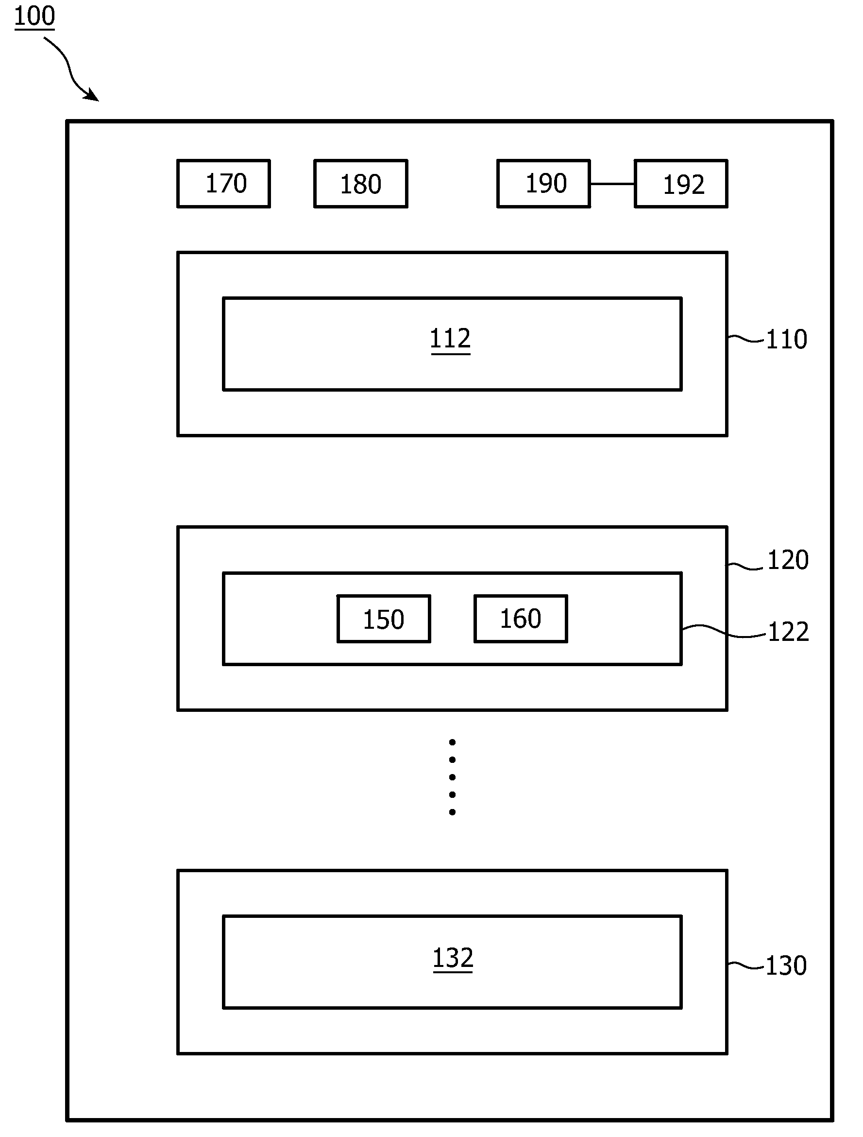
[0021]In the following description, FIG. 1 is used to illustrate several window blinds according to several embodiments of the present invention, and different modules will be described in detail accompanying with different embodiments. Incorporating all modules in one figure is just for the simplicity of the description, and should not be understood that each module in FIG. 1 is essential for the present invention.

[0022]In the first embodiment shown in FIG. 1, a window blind 100 comprises a plurality of slats 110, 120, and 130 and a plurality of solar cells 112, 122, and 132. Each solar cell is configured to collect solar energy and convert it into electricity. Each solar cell can be mounted on a corresponding slat, and the mount can be rigid, which means that the movements of the slat and the solar cell are synchronous, or the mount can be flexible, which means that the movements of the slat and the solar cell can be asynchronous. In the latter situation, the posture of each solar...


PUM


Abstract

The present invention proposes a posture-adjustable solar-collecting window blind, which can adjust the position of solar cells to better collect solar energy. In the window blind, a solar detector and an ampere meter are used to detect the relationship between the incident angle of sunlight and an optimal arrangement of the solar detector. The relationship can be further used to adjust the positions of the plurality of solar cells. Furthermore, the window blind comprises a light sensor to detect the light intensity of a target area, which can be complementarily used to adjust the position of the plurality of solar cells.

Description

FIELD OF THE INVENTION[0001]The present invention relates to window blinds capable of collecting solar energy, in particular window blinds comprising posture-adjustable solar panels.BACKGROUND OF THE INVENTION[0002]Windows are an important part of our houses. One of their main functions is to allow sunlight to pass into the inside of houses or block the entrance of sunlight. Recently ideas have been developed for installing solar panels in windows to collect solar energy and convert it into electricity. Among them, SHARP's LumiWall product combines solar power generation, daylight transmission and illumination. In a LumiWall product, a number of thin-film solar panels are embedded inside the glass to convert solar energy into electricity during daytime hours, and provide illumination as white-LED during nighttime. A LumiWall product will not really generate much electricity for use in house; its aim is to create an aesthetically-pleasing, self-contained illumination device.[0003]How...

Claims


Application Information

Patent Timeline
Patent Type & Authority Patents(United States)
IPC IPC(8): E05F15/20F24S50/20H02S30/20
CPCF24J2/0433Y02E10/50H01L31/042F24J2/38E06B2009/6827E06B2009/2476E06B9/24H01L31/045Y02E10/47Y02B10/20H02S30/20H02S20/32H02S20/30F24S20/63F24S50/20
Inventor BEREZHNYY, IGORDIEDERIKS, ELMO MARCUS ATTILA
Owner SIGNIFY HLDG BV
Why Eureka
Try Eureka