Wheel for a hydraulic machine, a hydraulic machine including such a wheel, and an energy conversion installation equipped with such a hydraulic machine

Inactive Publication Date: 2014-04-01
GE RENEWABLE TECH
View PDF6 Cites 0 Cited by
  • Summary
  • Abstract
  • Description
  • Claims
  • Application Information

AI Technical Summary

Benefits of technology

[0006]A particular object of the present invention is to remedy that drawback, by proposing a wheel of

Problems solved by technology

The cost of those components is thus neces

Method used


Image

  • Wheel for a hydraulic machine, a hydraulic machine including such a wheel, and an energy conversion installation equipped with such a hydraulic machine
  • Wheel for a hydraulic machine, a hydraulic machine including such a wheel, and an energy conversion installation equipped with such a hydraulic machine
  • Wheel for a hydraulic machine, a hydraulic machine including such a wheel, and an energy conversion installation equipped with such a hydraulic machine

Examples


Embodiment Construction

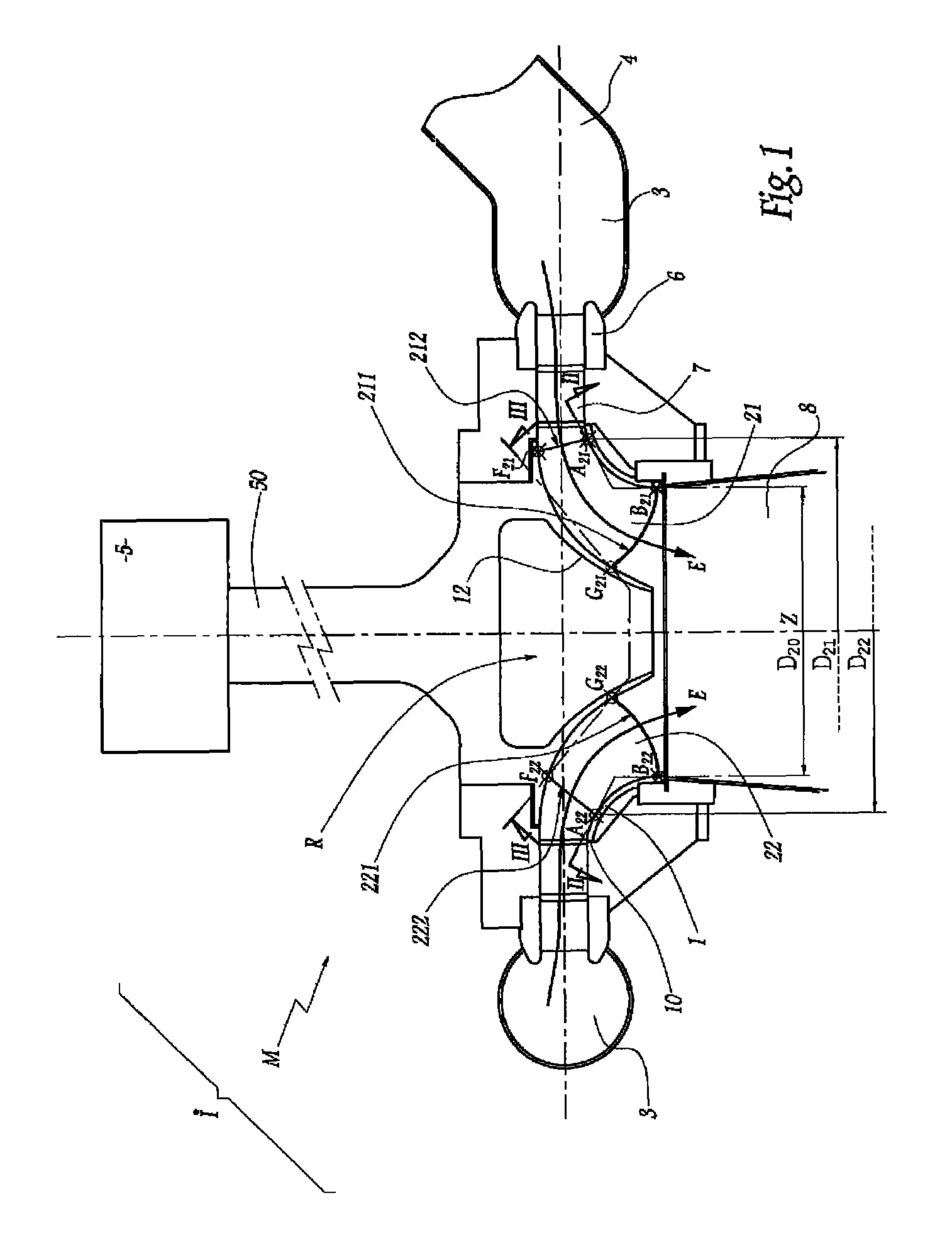
[0030]The installation i shown in FIG. 1 includes a reversible hydraulic machine M that is a Francis-type pump turbine whose wheel or “runner” R is fed with water from a casing 3 into which a forced-flow duct 4 opens out. In operation, the wheel R rotates about an axis of rotation Z that is vertical. In order to generate electricity in turbine mode, the machine M is coupled to an alternator 5 via a shaft 50 that rotates about the axis Z. Between the casing 3 and the wheel R there are disposed static stay vane blades 6 and steerable wicket gates 7 whose function is to guide a flow and to regulate the flow-rate of water E that is coming from the duct 4 and that is to pass through the wheel R towards a discharge conduit 8.

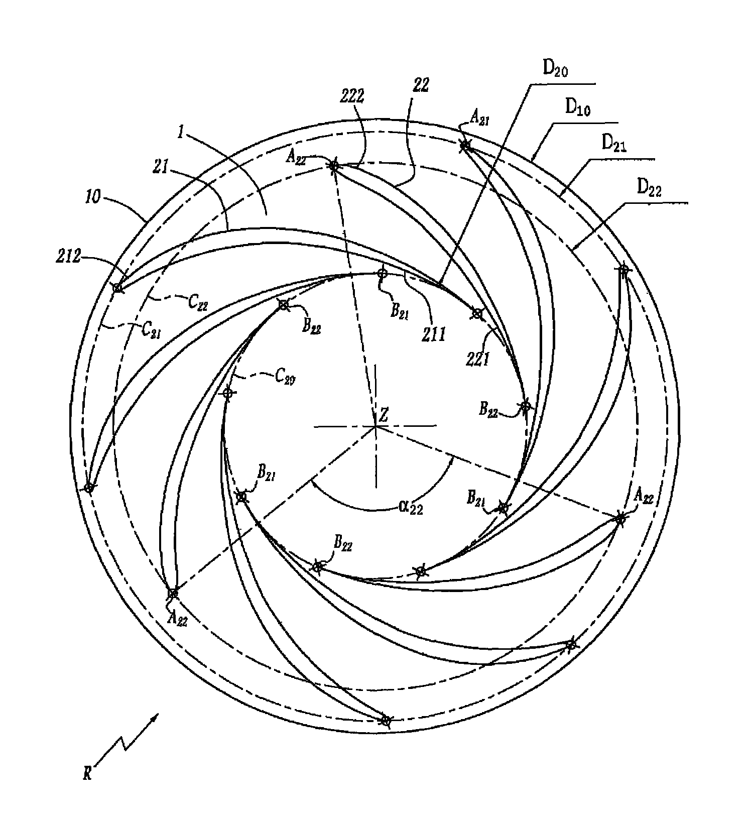
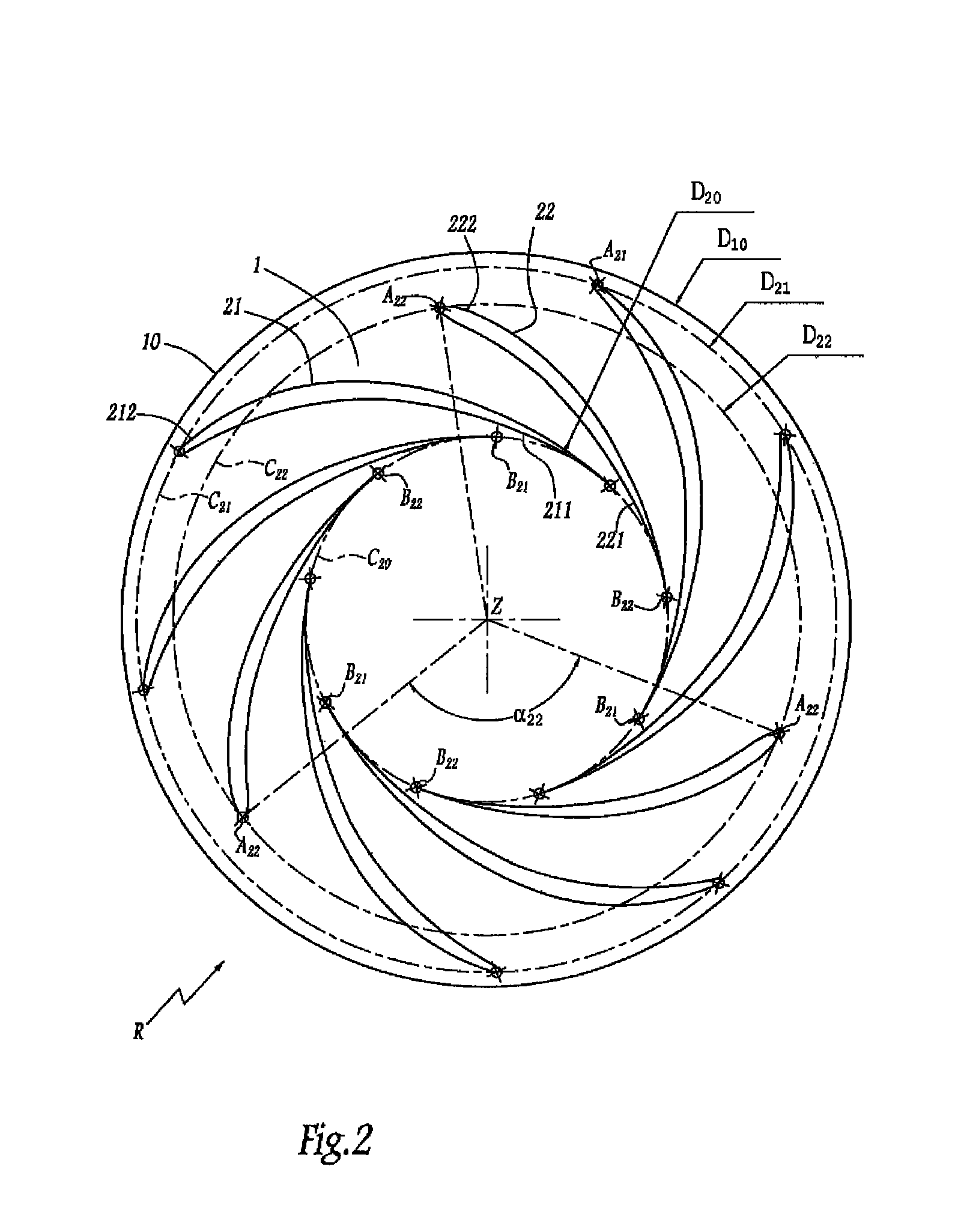
[0031]FIG. 2 shows a portion of the wheel R that includes a band 1 that is circularly symmetrical about the axis Z. The band 1 has an outside peripheral edge 10 of diameter D10. FIG. 3 shows a portion of the wheel R that includes a crown 12 that defines a central hole...


PUM


Abstract

The invention relates to a wheel (R) of the Francis type that comprises a ring (1) with revolution symmetry about the rotation axis (Z) of the wheel (R), and curved blades (21, 22) connected to the ring (1) and each having an outer peripheral edge (212, 222) and an inner central edge (211, 221). The connection points (B21, B22) between the ring (1) and the inner central edges (211, 221) of the blades (21, 22) are located on a same circle (C20) centered on the axis (Z). The connection points (A21, A22) between the ring (1) and the outer peripheral edges (212, 222) of the blades (21, 22) are located on at least two distinct circles (C21, C22) (D21, D22) centered on the axis (Z).

Description

BACKGROUND OF THE INVENTION[0001]1. Field of the Invention[0002]The present invention relates to a wheel of the Francis type for a hydraulic machine, which wheel is designed to pass a forced flow of water. Such a flow drives the wheel in rotation when the machine is a turbine. Such a flow results from said rotation when the machine is a pump. The present invention also relates to a hydraulic machine including such a wheel. The present invention also relates to an energy conversion installation equipped with such a hydraulic machine.[0003]2. Brief Description of the Related Art[0004]Document JP-A-2005 48608 describes a wheel or “runner” for a hydraulic machine of the pump-turbine type. That wheel has an axisymmetric band and a plurality of curved blades that are secured to or integral with the band and each of which has an outside peripheral leading edge and an inside central trailing edge. The connections via which the band is connected to the inside central edge of every other blad...

Claims


Application Information

Patent Timeline
IPC IPC(8): F01D5/04F03B3/02
CPCY02E10/28F01D5/048Y02E10/20
Inventor MAZZOUJI, FARIDCOUSTON, MICHEL HENRIHOUDELINE, JEAN BERNARDLAVIGNE, SYLVAINSEGOUFIN, CLAIRE
Owner GE RENEWABLE TECH
Why Eureka
Try Eureka