Compressor airfoil with tip dihedral

a compressor and tip dihedral technology, applied in the field of jet propulsion engines, can solve the problems of reducing the pressure rise of the compressor, high loss and blockage in the tip region of the compressor, and associated efficiency penalties

Active Publication Date: 2014-04-01
GENERAL ELECTRIC CO
View PDF26 Cites 27 Cited by
  • Summary
  • Abstract
  • Description
  • Claims
  • Application Information

AI Technical Summary

Problems solved by technology

This tip flow can roll up into a vortex, which tends to collect on the pressure side surface of the circumferentially adjacent blade, leading to high levels of loss and blockage in the compressor tip region.
As this blockage spreads across the compressor rotor tip, the ability of the compressor to produce a pressure rise decreases, and may result in a stall in some cases.
In the art, casing treatments, such as circumferential grooves have sometimes been used to control or reduce the tip leakage and improve stall margin, but with an associated efficiency penalty.
While these methods serve to reduce tip leakage flow levels, they do not control losses and blockage created by the remaining tip flow.

Method used


Image

  • Compressor airfoil with tip dihedral
  • Compressor airfoil with tip dihedral
  • Compressor airfoil with tip dihedral

Examples


Embodiment Construction

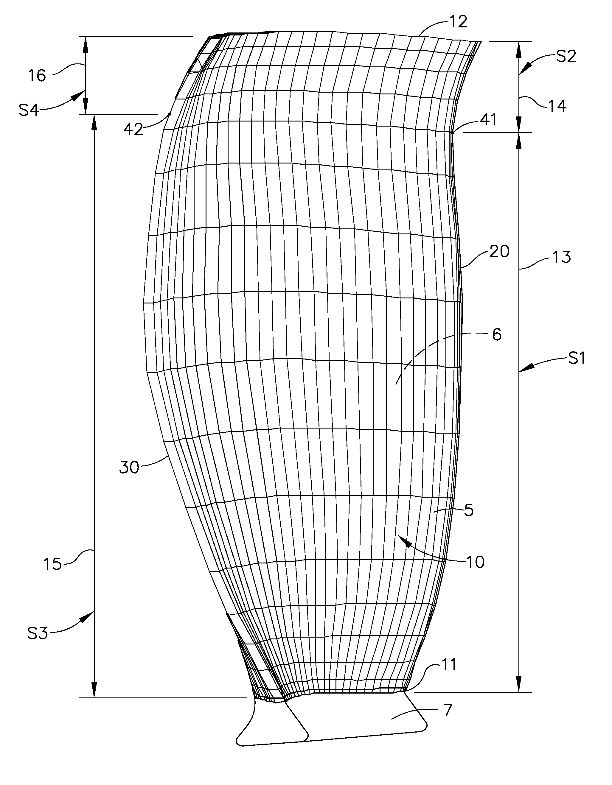
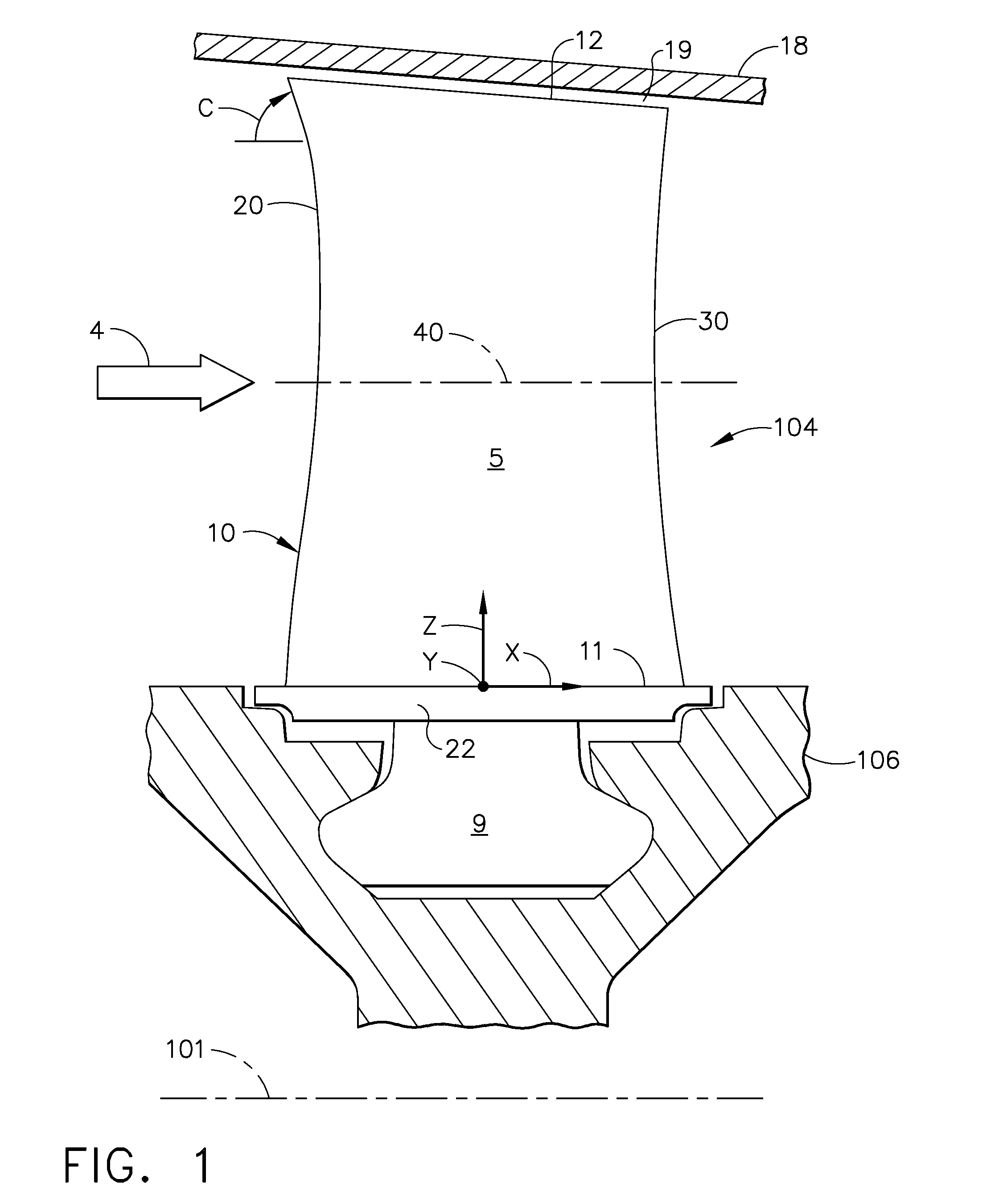
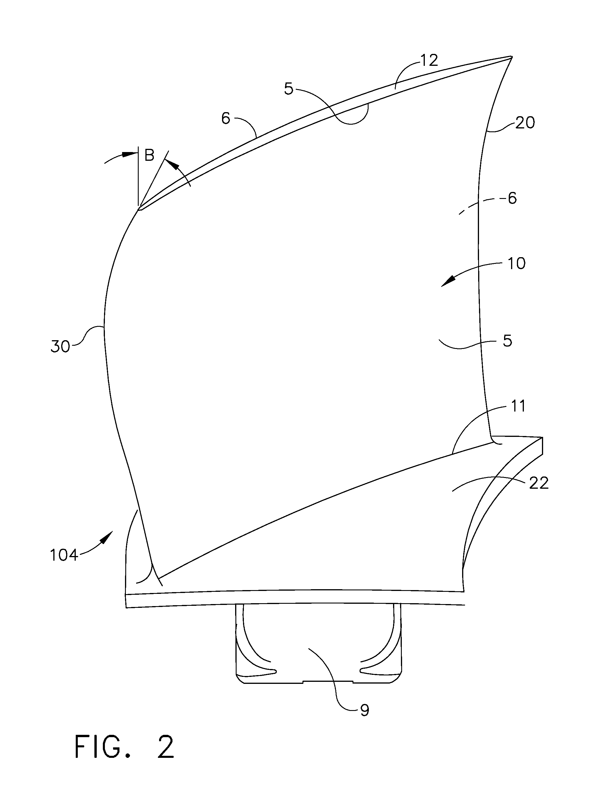
[0020]Referring to the drawings wherein identical reference numerals denote the same elements throughout the various views, FIG. 1 is a schematic cross-sectional view of a portion a partly sectional side view of a row of compressor rotor blades in a multistage axial compressor constructed according to an aspect of the present invention. FIG. 8 is a schematic cross-sectional view of a multi-stage compressor 100 having a row of compressor rotor blades 104 having airfoils 10 according an exemplary embodiment of the present invention, as described herein below.

[0021]Illustrated and shown in part in FIG. 8 is a row of compressor rotor stages 102 comprising compressor blades 104 suitably mounted to a compressor rotor 106 of a multistage axial compressor 100 in a gas turbine engine. The compressor 100 has several stages of stator vanes (shown as S1, S2, etc.) cooperating with corresponding compressor rotor blades (shown as R1, R2, etc.) which decrease in size in the downstream (axial) dire...


PUM


Abstract

An airfoil for a compressor is described. The airfoil has a root, an airfoil tip, a leading edge, a trailing edge, airfoil pressure and suction sides extending between the leading edge and the trailing edge. The airfoil has an inner span region and an outer span region and the trailing edge has a dihedral profile such that the trailing edge dihedral angle decreases in at least a portion of the inner span region and the outer span region.

Description

BACKGROUND OF THE INVENTION[0001]This invention relates generally to jet propulsion engines, and more specifically to compressor airfoils used therein.[0002]In a gas turbine engine air is pressurized in a compressor and mixed with fuel in a combustor for generating hot combustion gases. The combustion gases are discharged through turbine stages which extract energy therefrom for powering the compressor, and producing output power for use in driving a booster (low pressure compressor) and a fan in an exemplary turbofan aircraft engine application.[0003]A multistage axial compressor includes cooperating rows of stator vanes and rotor blades which decrease in size to pressurize air in stages. The compressor vanes and blades have corresponding airfoils which typically vary in configuration as their size decreases from stage to stage for maximizing performance of the compressor. Compressor performance includes, for example, efficiency of compression, flow capability, and stall margin, wh...

Claims


Application Information

Patent Timeline
Patent Type & Authority Patents(United States)
IPC IPC(8): F01D5/12
CPCF05D2240/304F05D2250/71F05D2240/122Y02T50/673F05D2240/121F05D2240/303F04D29/324F01D5/141Y02T50/60
Inventor BREEZE-STRINGFELLOW, ANDREWCLARK, DAVID SCOTTBEACHER, BRENT F.
Owner GENERAL ELECTRIC CO
Why Eureka
Try Eureka