Brush arrangement for electrical machine

a brush arrangement and electrical machine technology, applied in the field of electric machines, can solve the problems of high and achieve the effect of reducing power loss in upstream electronics

Active Publication Date: 2014-04-01
ROBERT BOSCH GMBH
View PDF12 Cites 22 Cited by
  • Summary
  • Abstract
  • Description
  • Claims
  • Application Information

AI Technical Summary

Benefits of technology

[0003]The invention is based on the object of reducing power losses in upstream electronics, voltage fluctuations in the vehicle power supply system and electromagnetic interference.

Problems solved by technology

It has been found that the operation of such conventional motors can lead to high power losses in upstream electronics, to voltage fluctuations in a vehicle power supply system, and to electromagnetic interference (EMC problems).

Method used


Image

  • Brush arrangement for electrical machine
  • Brush arrangement for electrical machine
  • Brush arrangement for electrical machine

Examples


Embodiment Construction

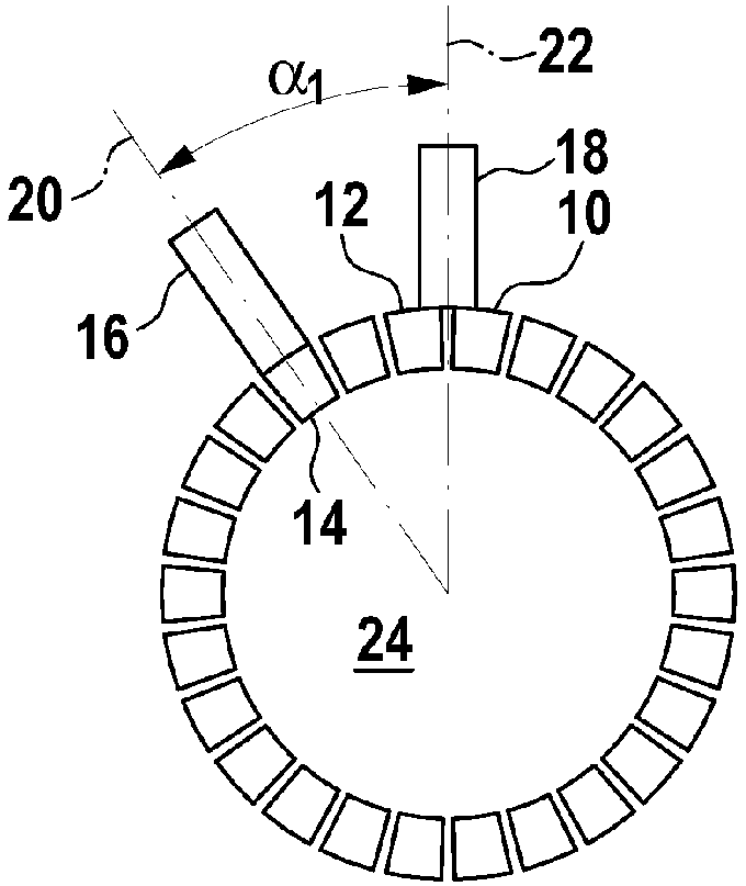
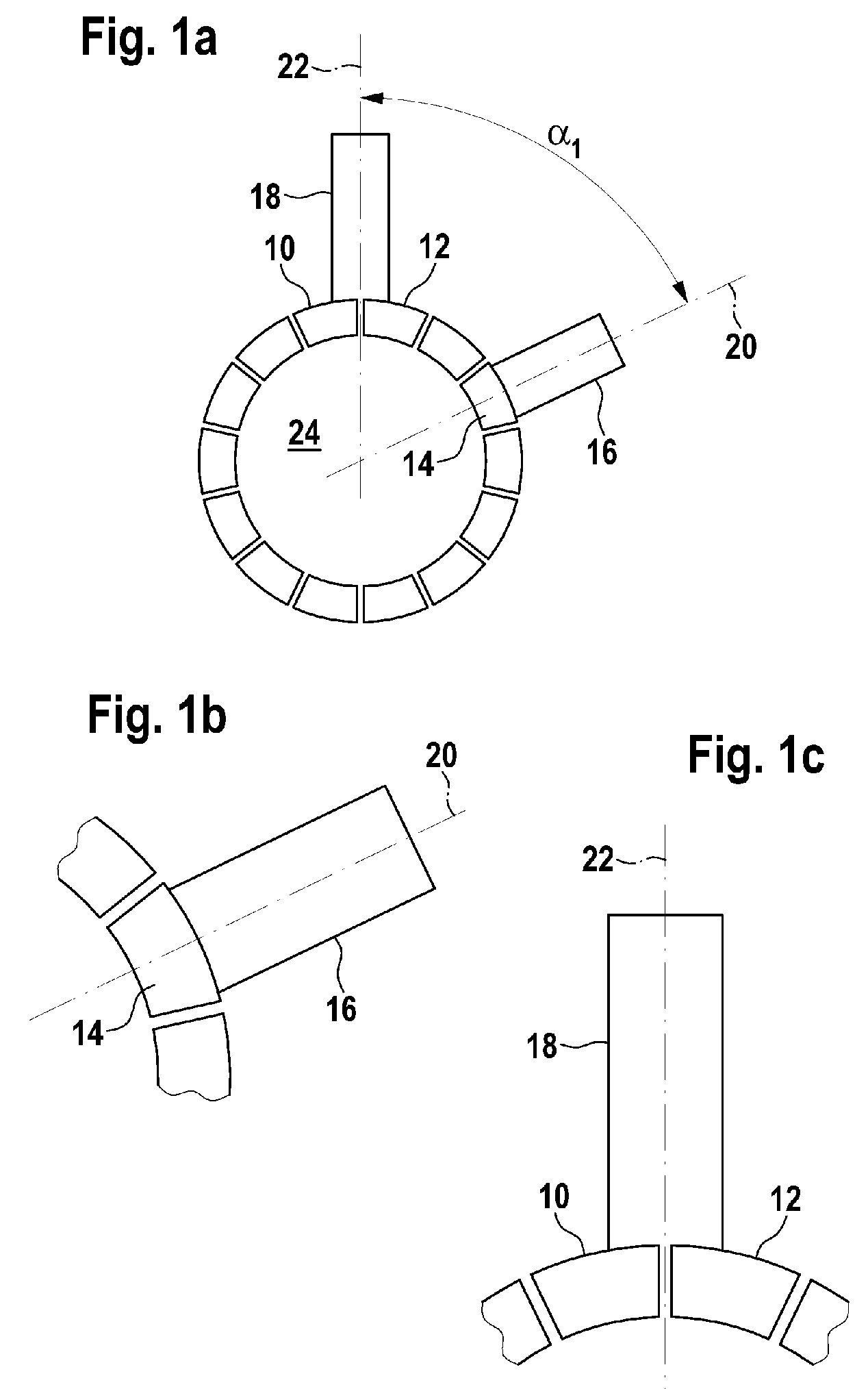
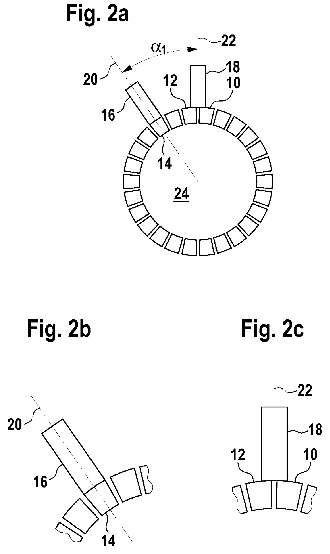
[0022]When using a wave winding, it is possible to choose a number of brushes less than the number of poles 2p without additional measures, with the characteristic of the electrical machine being changed only slightly. In the brush arrangement shown in FIG. 1a for a retrogressive simplex wave winding for a 6-pole motor with 14 commutator laminates 10, 12, 14 and two brushes 16, 18, a first circumferential angle α1 between a first radial axis 20 of the first brush 16 and a second radial axis 22 of the second brush 18 is approximately 64.3°. The second brush 18 is positioned symmetrically with respect to two commutator laminates 10, 12 (see FIG. 1c) when the rotor 24 assumes a rotor position 26 (see FIG. 3) where the first brush 16 is positioned centrally on a third commutator laminate 14 (see FIG. 1b). The term “laminate” is also used instead of “commutator laminate” in the following text. It is frequently expedient to arrange two brushes 16, 18 at as small an angle α1 with respect t...


PUM


Abstract

An electrical machine, in particular an electric motor, has a first number (k) of commutator laminates (10, 12, 14) and brushes (16, 18), wherein the commutator laminates (10, 12, 14) are arranged distributed uniformly in the circumferential direction of a circumference of a laminate support (24). The brushes (16, 18) are arranged such that commutation times are distributed as uniformly as possible in order to reduce current ripple when using a wave winding and a number of brushes (16, 18) which is less than a number of poles (2p) in the electrical machine.

Description

BACKGROUND OF THE INVENTION[0001]The invention relates to an electrical machine, in particular an electric motor wherein the electrical machine has a first number of commutator laminates and brushes, wherein the commutator laminates are arranged distributed uniformly in the circumferential direction on a circumference of a laminate support.[0002]DE 695 13 655 T2 describes two windshield wiper motors for two speeds in each case. One of the two motors has two poles and three brushes, with a high-speed brush being arranged offset through a circumferential angle of, for example 120° with respect to a common grounding brush. Here, the circumferential angle is chosen as a function of a desired ratio between a high speed and a low speed of the motor. The other motor has four poles and six brushes, with the high-speed brush being arranged offset through a circumferential angle of, for example, 60° with respect to the associated grounding brush, and with the circumferential angle also being ...

Claims


Application Information

Patent Timeline
Patent Type & Authority Patents(United States)
IPC IPC(8): H01R39/18
CPCH02K23/32H02K13/10
Inventor ROOS, GERALDBERNARD, PIERRE
Owner ROBERT BOSCH GMBH
Why Eureka
Try Eureka