Beam controller for aperture antenna, and aperture antenna therewith

a technology of aperture antenna and beam controller, which is applied in the direction of antennas, space-fed arrays, electrical devices, etc., can solve the problem that the horn antenna cannot form the antenna beam in the desired shape, and achieve the effect of reducing the manufacturing cost of the aperture antenna

Active Publication Date: 2014-04-01
LIG NEX1 CO LTD
View PDF8 Cites 171 Cited by
  • Summary
  • Abstract
  • Description
  • Claims
  • Application Information

AI Technical Summary

Benefits of technology

[0008]The present invention has been made in an effort to provide a beam controller easily forming a desired beam at low cost without changing the physical size of an antenna by using a beam shaping mechanism for inserting a multi-layer substrate into a single antenna and an aperture horn antenna therewith.

Problems solved by technology

However, a single antenna, a horn antenna cannot form the antenna beam in the desired shape until the physical sizes of the antenna are changed.

Method used


Image

  • Beam controller for aperture antenna, and aperture antenna therewith
  • Beam controller for aperture antenna, and aperture antenna therewith
  • Beam controller for aperture antenna, and aperture antenna therewith

Examples


Embodiment Construction

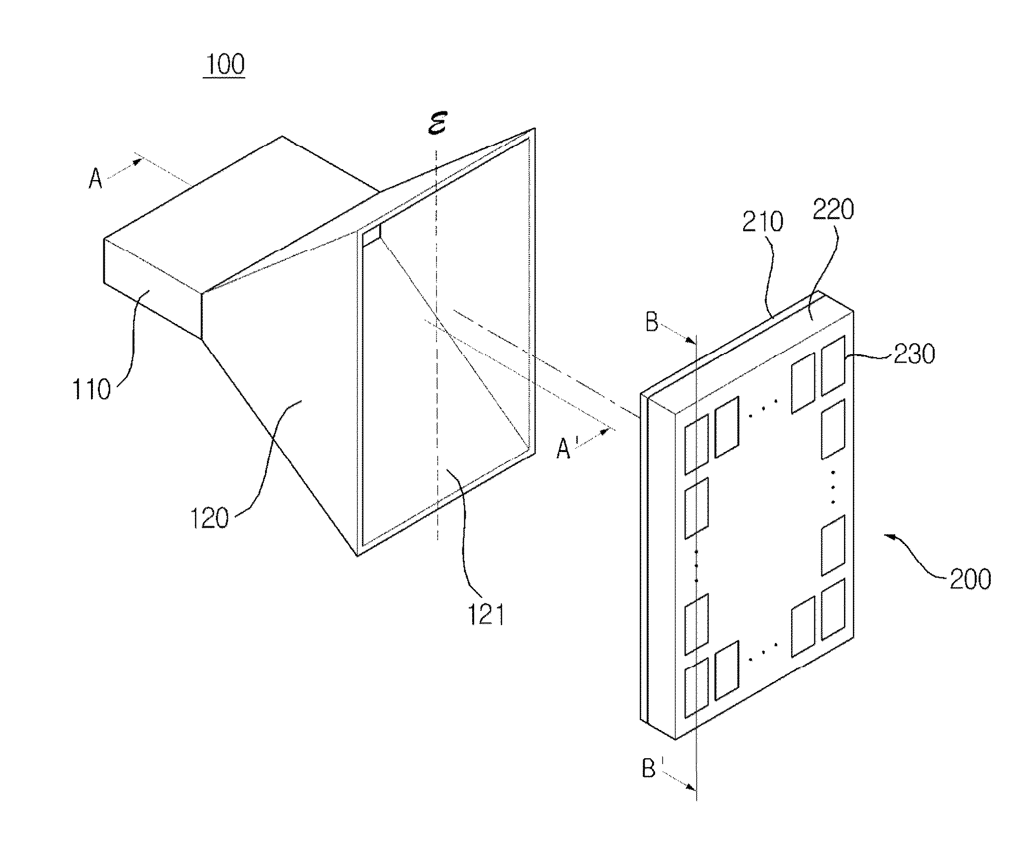
[0040]Hereinafter, exemplary embodiments of the present invention will be described in detail with reference to the accompanying drawings. First of all, it is to be noted that in giving reference numerals to elements of each drawing, the same reference numerals refer to the same elements even though the same elements are shown in different drawings. Further, in describing the present invention, the relevant well-known functions or constructions will not be described in detail in a case where it is judged that they may obscure the gist of the present invention, and the terminologies described in a singular include the plural concept. Hereinafter, the exemplary embodiment of the present invention will be described, but it will be understood to those skilled in the art that the spirit and scope of the present invention are not limited thereto and various modifications and changes can be made.

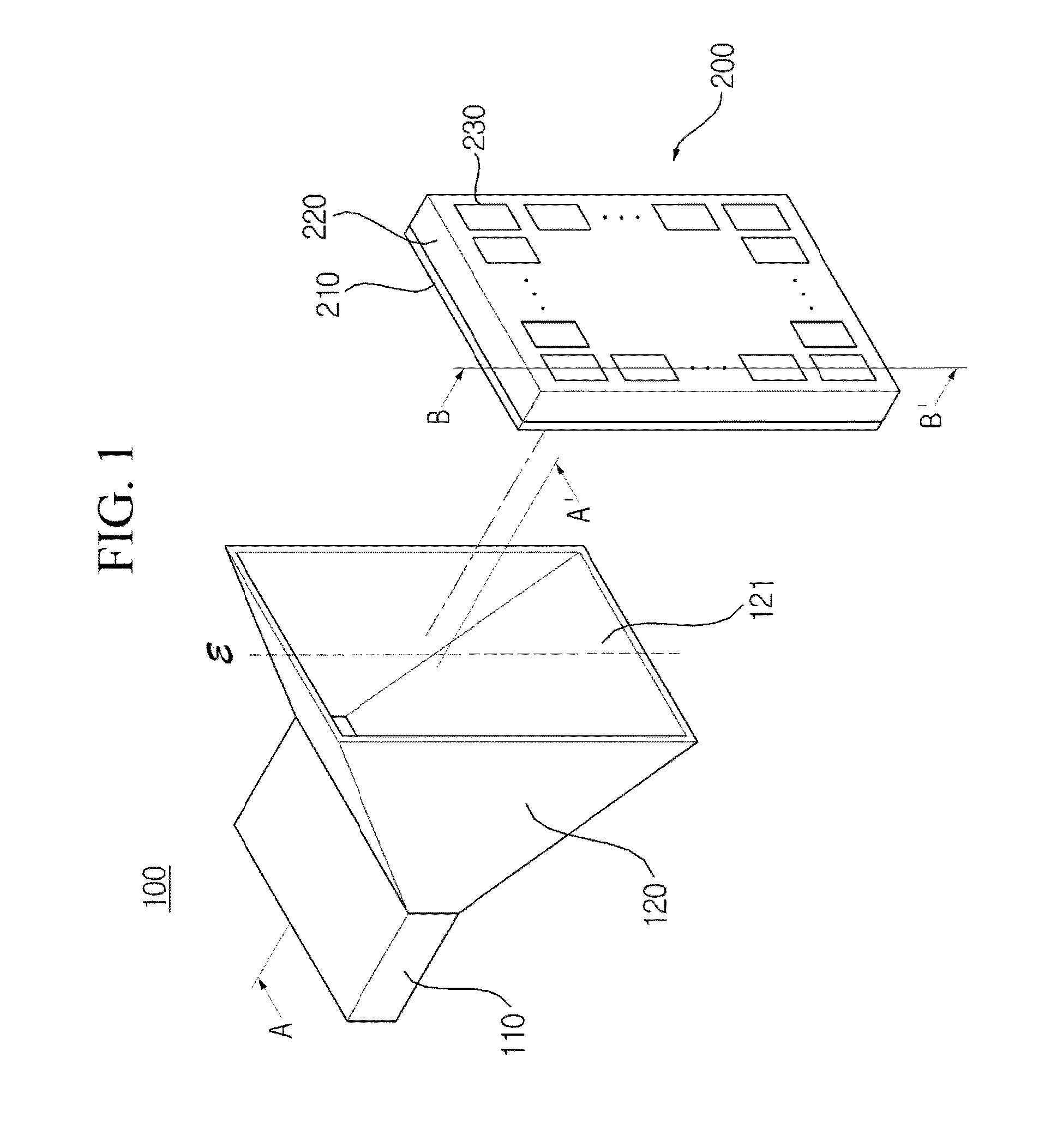
[0041]FIG. 1 is an exploded perspective view of an aperture horn antenna including a beam contr...


PUM


Abstract

The present invention relates to an aperture antenna capable of controlling a shape of a radiated beam without changing a structure of an aperture antenna by connecting a beam controller with a single aperture antenna. the aperture antenna including a beam controller according to the present invention includes: a waveguide; an aperture horn of which one end is connected to the waveguide and the other end is provided with an opening; and a beam controller including a feeding unit connected to the opening and provided with a plurality of slits, a dielectric layer connected to the feeding unit, and a plurality of patches connected to the dielectric layer to control a beam shape of a signal introduced into the feeding unit and radiated through the patches.

Description

BACKGROUND OF THE INVENTION[0001]1. Field of the Invention[0002]The present invention relates to a beam controller for an aperture antenna and an aperture antenna therewith, and more particularly, to a beam controller formed with a plurality of slits and a plurality of patches and an aperture antenna therewith to form an antenna beam in a desired form.[0003]2. Description of the Related Art[0004]Generally, an antenna radiates and receives radio waves into and from a free space. A standard for classifying the antenna is various. Typically, the antenna may be classified into a linear antenna, an aperture antenna, a microstrip antenna, an array antenna, a reflector antenna, a lens antenna, or the like.[0005]The radio waves radiated from the antenna have a predetermined pattern, wherein the polarization of the radiated radio wave may be classified into a linearly polarized wave, a circularly polarized wave, an elliptically polarized wave, etc., according to a direction in which an elect...

Claims


Application Information

Patent Timeline
Patent Type & Authority Patents(United States)
IPC IPC(8): H01Q13/00
CPCH01Q19/08H01Q21/065H01Q21/0018H01Q13/0225H01Q13/06
Inventor KIM, YOUNG, WAN
Owner LIG NEX1 CO LTD
Why Eureka
Try Eureka