Fluid flow monitor

a technology of fluid flow monitor and monitor, which is applied in the direction of liquid/fluent solid measurement, volume/mass flow by dynamic fluid flow effect, indication/recording movement, etc., can solve the problems of large water waste, leakage of pipes or inefficient plumbing, and accidental left-on of burst pipes or taps

Active Publication Date: 2014-04-08
AQUATRIP
View PDF26 Cites 8 Cited by
  • Summary
  • Abstract
  • Description
  • Claims
  • Application Information

AI Technical Summary

Benefits of technology

[0015]The magnet preferably is a corrosion proof ferrite magnet. The magnet may include a weight to limit the displacement of the magnet to an excessive distance past the predetermined distance and to assist in returning the magnet to a non-displaced position. This weight may be made from brass.
[0022]The shut-off valve may also be a latching solenoid valve which includes a magnet whereby when electrical current is applied to the coil, the valve either latches or delatches the plunger depending on the polarity of the magnetic field and the direction of the current flow. When current polarity is reversed, if the plunger is in a latched state, it will be delatched or vice versa. One advantage of a latching solenoid is that only a small electrical pulse is required. This makes it ideal for use with a DC powersource, such as a battery.

Problems solved by technology

Though wastage can occur in a number of places, one of the largest contributors to this problem is unknown leaks in pipes or inefficient plumbing, such as dripping taps.
These problems may appear small, but over a long period of time it leads to copious amounts of water being wasted.
In addition, burst pipes or taps being accidentally left on are also a considerable problem, especially gone unnoticed.
If an owner is “away” then the system may only allow about 30 seconds of water supply.
This system only monitors the detection of leaks and does not monitor normal water usage in a household as the check-valve would remain open.

Method used


Image

  • Fluid flow monitor
  • Fluid flow monitor
  • Fluid flow monitor

Examples


example 2

[0065]FIGS. 3 to 6 illustrate a second embodiment of a fluid flow monitor 30 according to the invention as described above. In particular these figures illustrate a water flow monitor 30. FIGS. 3 to 5 depict a pictorial illustration of the water flow monitor 30 and FIG. 6 depicts a flow chart of the operation of the water flow monitor 30.

[0066]In this embodiment, the water flow monitor 30 may be incorporated into a water supply system such as the main water supply to a household or commercial establishment and is able to shut off the water supply automatically to the property in the event of excessive water flow such as accidental damage to the plumbing or if a tap is left on inadvertently. In addition, it is able to sense slow fluid flow such as may be indicative of a leak or dripping tap. Suitably, the water flow monitor 30 is installed directly after the water meter on the respective property's incoming water supply.

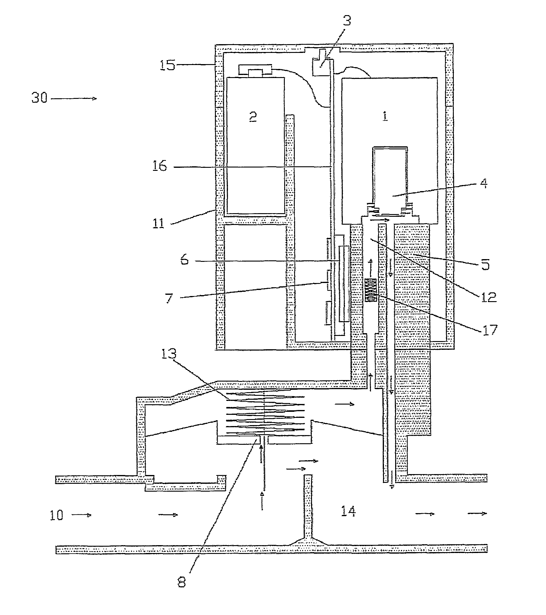
[0067]The water flow monitor 30 comprises a diaphragm valve 8,13...


PUM


Abstract

A fluid flow monitor, typically for water, includes the combination of a fluid conduit including a magnet displaceable within the conduit when fluid flows therethrough, an electric circuit having a power supply, a magnetic sensor switch positioned in the electric circuit located adjacent to the conduit and positioned at a predetermined distance from the magnet when the magnet is not displaced and a timer connected to the electric circuit. When the magnet is displaced the predetermined distance, the magnetic sensor switch closes the electric circuit activating the timer and when the magnet is not displaced to the predetermined distance, the magnetic sensor switch opens the electric circuit deactivating the timer.

Description

FIELD OF THE INVENTION[0001]The present invention relates to a fluid flow monitor, and in particular to a timer-controlled fluid flow monitor with a shut-off valve that can be utilized to monitor and control usage of fluids and / or leaks within a fluid supply system.DESCRIPTION OF THE PRIOR ART[0002]Water is one of the most valuable resources on the planet, so it is imperative to have means and techniques which assist and prevent wastage of this precious commodity. Though wastage can occur in a number of places, one of the largest contributors to this problem is unknown leaks in pipes or inefficient plumbing, such as dripping taps. These problems may appear small, but over a long period of time it leads to copious amounts of water being wasted. In addition, burst pipes or taps being accidentally left on are also a considerable problem, especially gone unnoticed.[0003]One current system that monitors water and provides a shut-off system for excessive water flow is the FloLogic® system...

Claims


Application Information

Patent Timeline
Patent Type & Authority Patents(United States)
IPC IPC(8): F16K31/48
CPCG01F1/28G01P13/002G01F15/001Y10T137/86397Y10T137/7761
Inventor MEIKLE, ANDREW, STUART
Owner AQUATRIP
Why Eureka
Try Eureka