

Head for dispensing a liquid as a drip
a technology for dispensing a liquid as a drip, which is applied in the direction of liquid transferring devices, instruments, volume meters, etc., can solve the problem of obstructed airflow
- Summary
- Abstract
- Description
- Claims
- Application Information
AI Technical Summary
Benefits of technology
Problems solved by technology
Method used
Image

Examples
Embodiment Construction
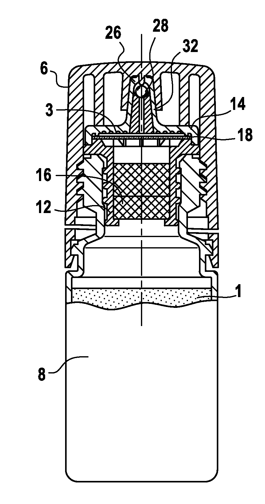
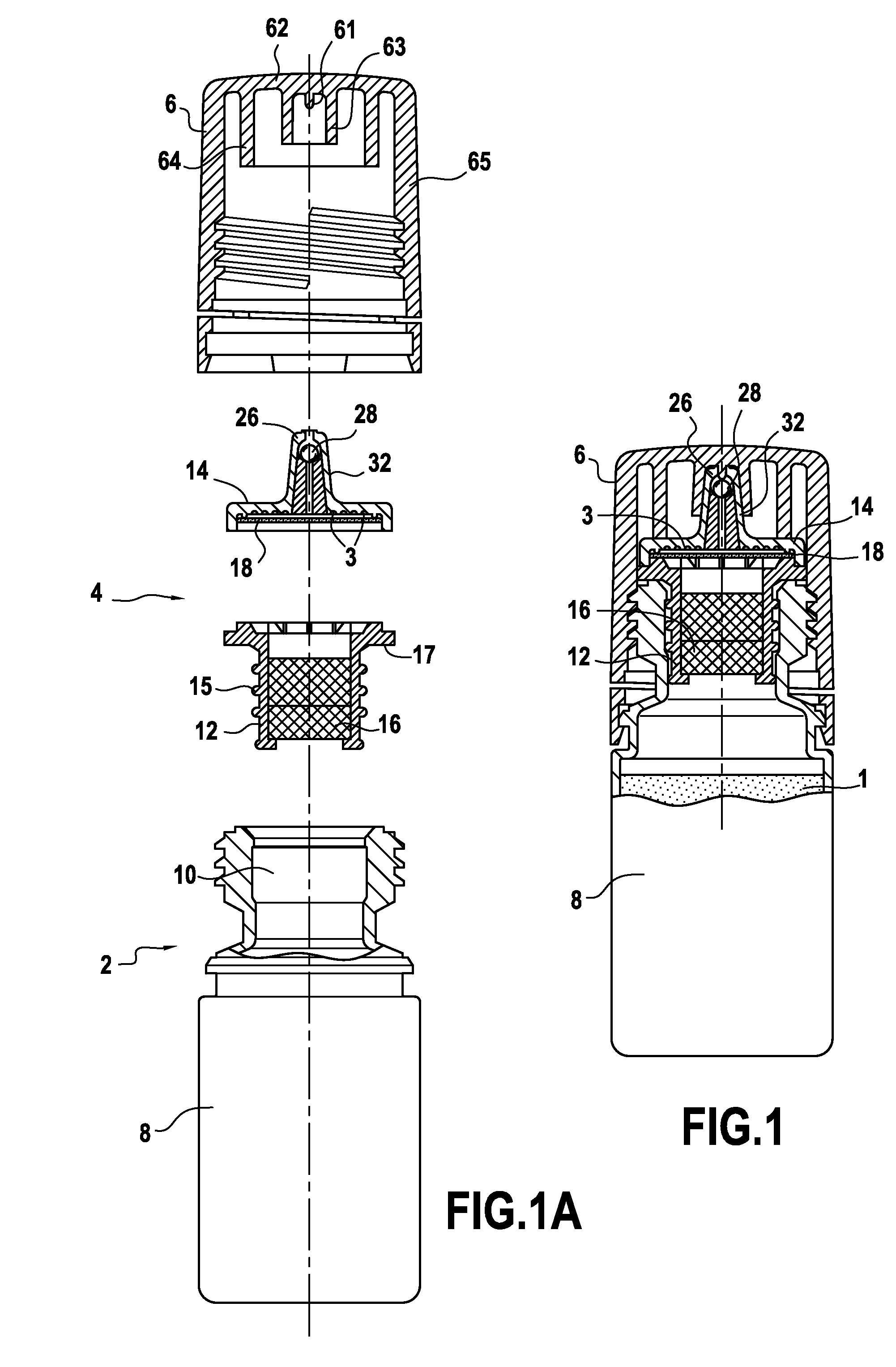
[0019]A bottle for packaging a liquid to be delivered drop by drop is illustrated in FIGS. 1 and 1A in the form of a bottle designed more particularly for conditioning a collyrium (eye-drop aqueous composition). The composition of the latter may advantageously satisfy a formula containing no preservative, because of the high quality of the antibacterial preservation provided according to the invention.
[0020]This bottle according to the invention comprises a receptacle 2 with a liquid-storage reservoir 8 inside it and a liquid delivery head 4 that is mounted in a neck 10 of the receptacle at an end of the reservoir and closes that reservoir. A removable cap 6 is provided for covering the delivery head when the bottle is not being used by a user. The neck 10 has a thread on its outside surface that is provided for cooperating with a thread of the removable cap for closing the bottle.
[0021]The reservoir 8 comprises a cylindrical peripheral wall with reversible elastic deformation. This...
PUM
 Abstract
Description
Claims
Application Information