Modulated physical and chemical sensors
a chemical sensor and module technology, applied in the field of modules of physical and chemical sensors, can solve the problems of background intracellular fluorescence, most fluorescent indicator dyes, and most fluorescent dyes, and achieve the effect of broad excitation
- Summary
- Abstract
- Description
- Claims
- Application Information
AI Technical Summary
Problems solved by technology
Method used
Image
Examples
example 1
Methods of Generating Non-Spherical Microparticles
[0216]This Example describes methods for the generation of aspherical microparticles from spherical microparticles.
[0217]Fluorescent polystyrene microspheres 3.4 μm in diameter were purchased from Bangs labs. Polystyrene microspheres containing ferromagnetic chromium dioxide 2 μm and 4.4 μm in diameter were purchased from Spherotech. Iron oxide nanoparticles were obtained from Magnox. Fluorescent decyl methacrylate and silica sol gel nanospheres were polymerized in our lab. Glass microscope slides were purchased from Fisher Scientific.
[0218]Polystryrene microspheres were deposited onto a microscope slide and the slide was clamped to a laser table. A second slide was placed on top to sandwich the particles. The top slide was then moved laterally while applying pressure with the fingers (FIG. 10a). With a low concentration of particles and small lateral motions, single particle rolls are formed, while with a high concentration of parti...
example 2
Generation of MagMOONs
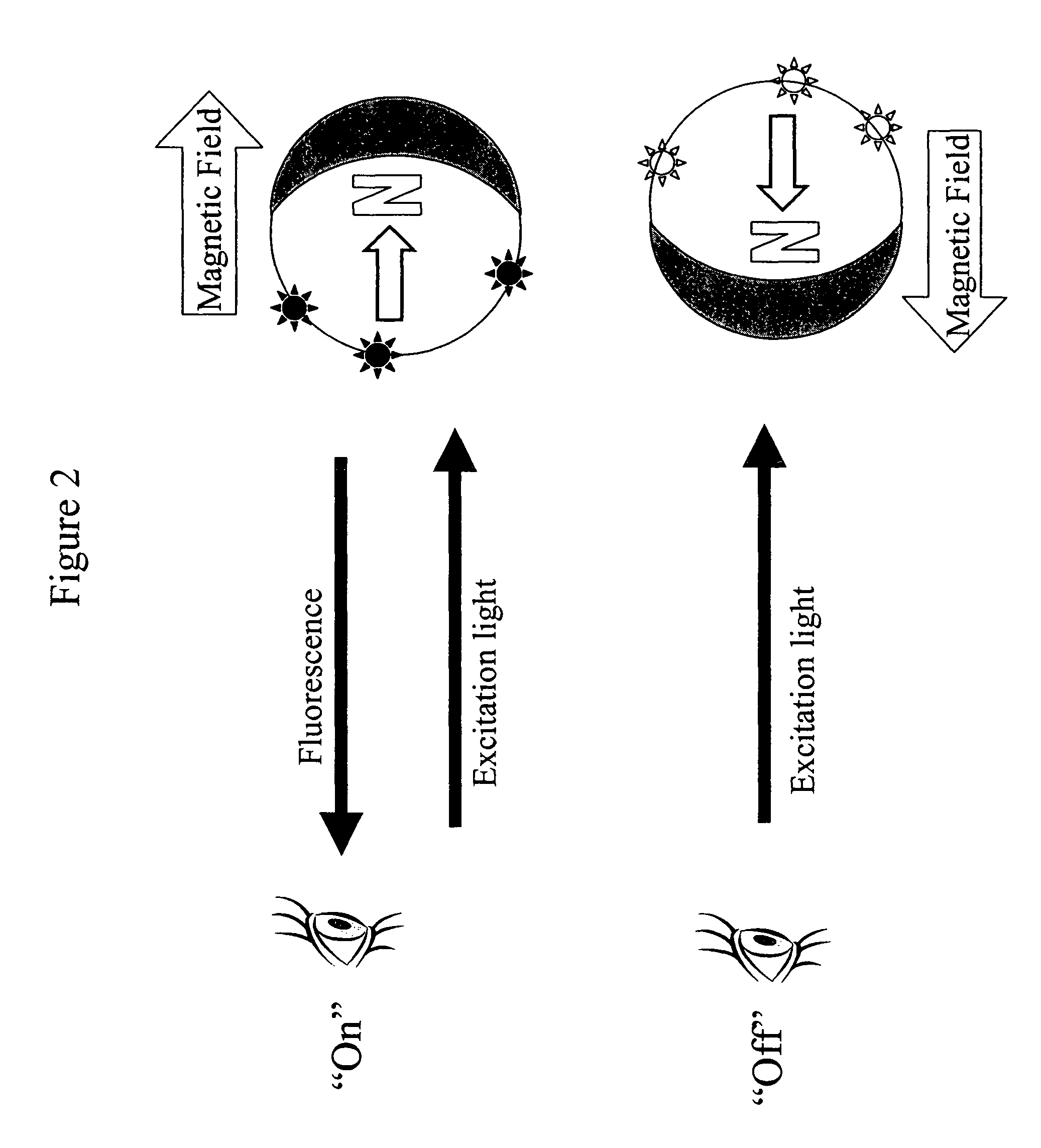
[0224]This example describes the generation of gold-capped streptavidin MagMOONs. The MagMOONs were then immersed in solutions a fixed concentration of Oregon Green labeled biotin (OG) and a varying concentration of Phycoerythrin labeled biotin (PE). A 20 μl drop of each solution was placed on a silanized glass microscope slide (silanized to keep the drop compact). A stepper motor rotated a cylindrical magnet in two orientations to orient the MagMOONs “on” and “off,” while a CCD camera was used to take fluorescence of the MagMOONs in “on” and “off” states. A blue excitation source from a mercury lamp, and 4× lens on a microscope was used. The focus of the microscope was raised to particles floating in solution to avoid viewing polystyrene particles that were adhered to the silanized glass. No washing step was performed. This example demonstrates that, by rotating the MagMOONs, it is possible to separate the MagMOON fluorescence from background fluorescence due ...
example 3
Generation of Metal-Capped MagMOONs
[0225]Fluorescent polystyrene microspheres 4.4 μm in diameter containing ferromagnetic material (Spherotech, Libertyville Ill.) were deposited on a microscope slide and one hemisphere of the particles is coated with either vapor deposited aluminum or sputter coated gold. The metal layer prevents excitation light from entering and fluorescence from leaving the coated side of the particle. It is preferred that the metal layer is thicker than the skin depth of the excitation or emission light, although thinner layers will still allow modulation. In this example, aluminum layers 100 nm thick (skin depth on the order of 20 nm) were used. Quenching of the dye molecules by the metal is not a problem since most of the dyes are not in immediate proximity (<10 nm) to the metal. The microspheres are magnetized so that their north side is uncoated. The particles were then removed from the slide with a paint brush and suspended in solution by sonication. When i...
PUM
| Property | Measurement | Unit |
|---|---|---|
| diameter | aaaaa | aaaaa |
| diameter | aaaaa | aaaaa |
| diameter | aaaaa | aaaaa |
Abstract
Description
Claims
Application Information
 - R&D
- Intellectual Property
- Life Sciences
- Materials
- Tech Scout
- Unparalleled Data Quality
- Higher Quality Content
- 60% Fewer Hallucinations
Browse by: Latest US Patents, China's latest patents, Technical Efficacy Thesaurus, Application Domain, Technology Topic, Popular Technical Reports.
© 2025 PatSnap. All rights reserved.Legal|Privacy policy|Modern Slavery Act Transparency Statement|Sitemap|About US| Contact US: help@patsnap.com


