
LED backlight driving circuit

a technology of led backlight and driving circuit, which is applied in the direction of instruments, light sources, electroluminescent light sources, etc., can solve the problems of adding to costs, and achieve the effects of improving the voltage boosting efficiency of led backlight driving circuit, reducing costs, and increasing duty ratio

Active Publication Date: 2014-04-15
TCL CHINA STAR OPTOELECTRONICS TECH CO LTD
View PDF9 Cites 0 Cited by
  • Summary
  • Abstract
  • Description
  • Claims
  • Application Information

AI Technical Summary

Benefits of technology

This solution enhances voltage boosting efficiency and reduces costs by eliminating the need for additional components, maintaining efficiency even at high voltage levels without increasing the duty ratio, thus providing a cost-effective and efficient LED backlight driving solution.

Problems solved by technology

However, when the load becomes greater as the number of LEDs increases, a plurality of boost circuits must be used instead of the single boost circuit to power the LEDs, which adds to the cost.

Method used


Image

  • LED backlight driving circuit
  • LED backlight driving circuit
  • LED backlight driving circuit

Examples


Embodiment Construction

[0047]It shall be understood that, the embodiments described herein are only intended to illustrate but not to limit the present disclosure.

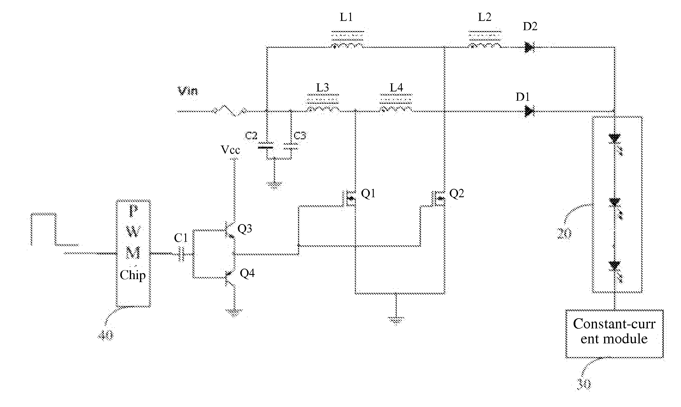
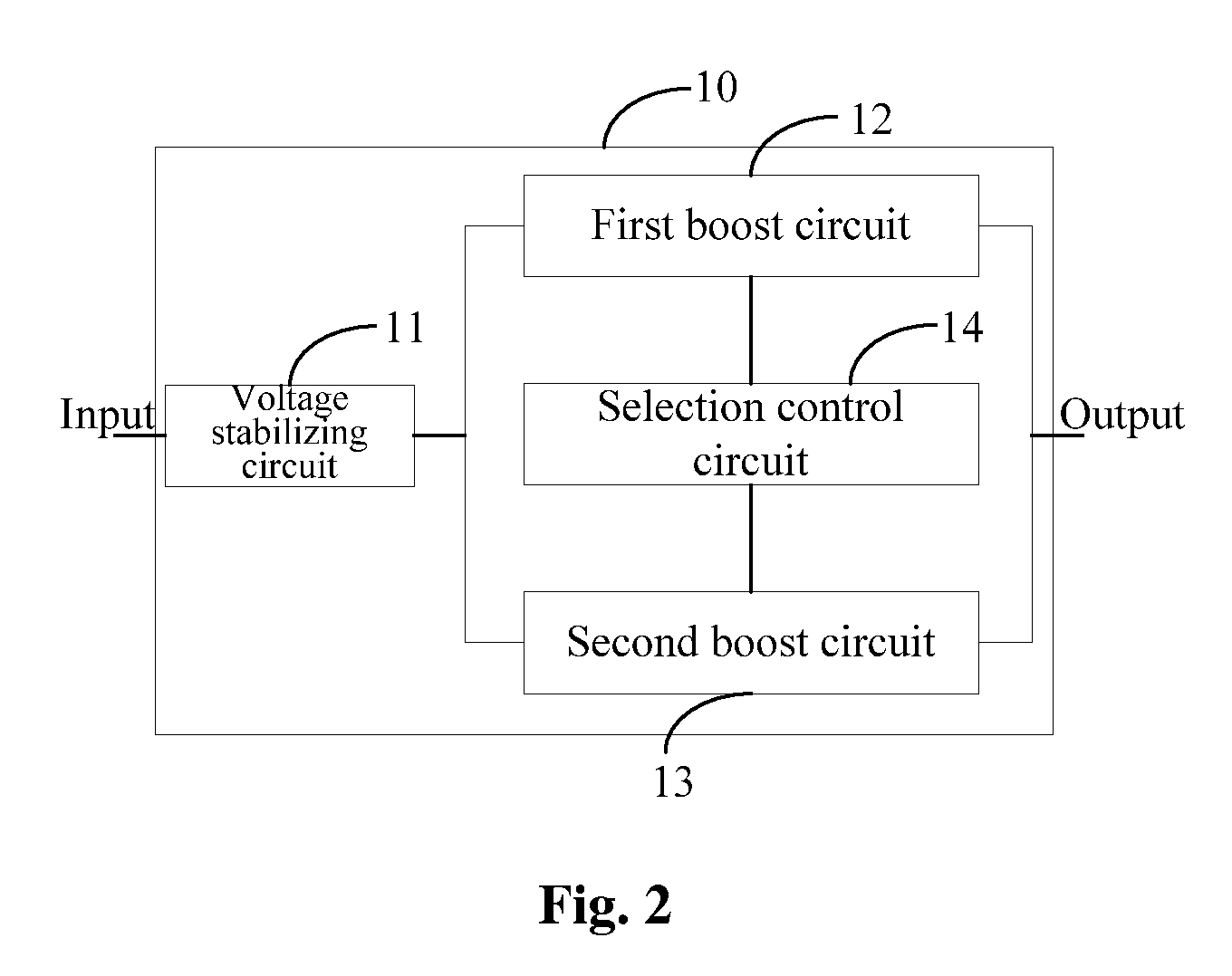
[0048]Referring to FIG. 2, the present disclosure provides an embodiment of a light emitting diode (LED) backlight driving circuit 10. The LED backlight driving circuit 10 is configured to power an LED backlight module (not shown), and comprises: a voltage stabilizing circuit 11, a first boost circuit 12, a second boost circuit 13 and a selection control circuit 14. The voltage stabilizing circuit 11 is configured to receive an input voltage and filter the input voltage to output a stabilized direct current (DC) voltage. The first boost circuit 12 is configured to receive the stabilized DC voltage and boost the stabilized DC voltage for output to the LED backlight module. The second boost circuit 13 is configured to receive the stabilized DC voltage and boost the stabilized DC voltage for output to the LED backlight module. The selection control...


PUM


Abstract

A light emitting diode (LED) backlight driving circuit is disclosed in the present disclosure. The LED backlight driving circuit in configured to power an LED backlight module, and comprises: a voltage stabilizing circuit, being configured to receive an input voltage and filter the input voltage to output a stabilized direct current (DC) voltage; a first boost circuit and a second boost circuit connected with the voltage stabilizing circuit respectively, being configured to receive the stabilized DC voltage and boost the stabilized DC voltage for output to the LED backlight module; and a selection control circuit, being configured to alternately select one of the first boost circuit and the second boost circuit to power the LED backlight module. The LED backlight driving circuit of the present disclosure can improve the voltage boosting efficiency and reduce the cost, so it is of great utility.

Description

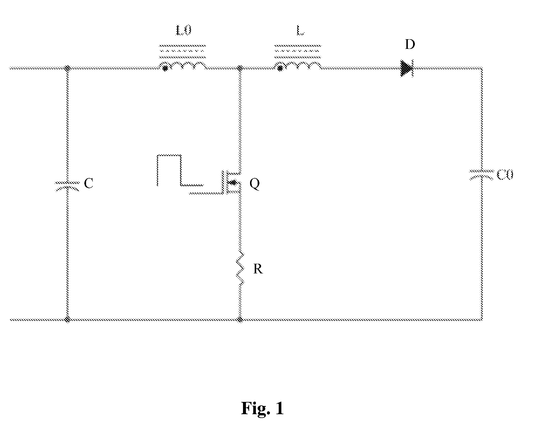
BACKGROUND[0001]1. Technical Field[0002]The present disclosure relates to the technical field of light emitting diode (LED) driving circuits, and more particularly, to an LED backlight driving circuit.[0003]2. Description of Related Art[0004]In the prior art LED backlight driving circuits, a boost circuit (i.e., a boost converter or step-up converter) is usually used to power an LED.[0005]Referring to FIG. 1, the boost circuit comprises a first inductor L0, a second inductor L, a diode D, a first capacitor C0, a second capacitor C, a metal-oxide-semiconductor field-effect transistor (MOSFET) Q and a resistor R. Herein, the MOSFET is simply called MOS transistor. The first inductor L0, the second inductor L, the diode D and the first capacitor C0 are connected in series with each other in sequence and then connected in parallel with the second capacitor C. A branch formed by the MOS transistor Q connected in series with the resistor R has one end connected between the first inductor ...

Claims


Application Information

Patent Timeline
Patent Type & Authority Patents(United States)
IPC IPC(8): H05B37/02
CPCH05B33/0815H05B33/0824H05B45/44H05B45/3725
Inventor GAO, XINMINGYANG, XIANG
Owner TCL CHINA STAR OPTOELECTRONICS TECH CO LTD
Learn More