Pressure relief valve and high pressure pump with such valve

a pressure relief valve and high-pressure pump technology, which is applied in the direction of positive displacement liquid engines, electrical control, servomotors, etc., can solve the problems of excessive inability of injectors to perform fuel injection operation, damage to the delivery pipe, etc., to achieve the effect of reducing the fuel pressure in the high-pressure side fuel passage, reducing the fuel pressure in the delivery pipe, and increasing the valve closing speed of the valve member

Active Publication Date: 2014-04-22
DENSO CORP
View PDF21 Cites 3 Cited by
  • Summary
  • Abstract
  • Description
  • Claims
  • Application Information

AI Technical Summary

Benefits of technology

[0017]According to the above feature of the invention (the feature of the claim 1), a size, a shape, an angle and the like of the notched portions and the fuel inlet ports are properly adjusted so that the differential pressure is generated between the fuel inlet chamber and the fuel passage at the downstream of the valve member when the pressure relief valve is opened. As a result, the dynamic pressure of the fuel, which has entered into the fuel inlet chamber from the fuel passage at the upstream of the valve member, is applied to the pressure receiving portion and the valve member is moved by an appropriate stroke amount in a short time period. In other words, when the stroke amount as well as a valve opening speed of the pressure relief valve is properly adjusted, it becomes possible to return the fuel from the high-pressure side fuel passage to the low-pressure side fuel passage, wherein a flow amount of such return fuel is equal to or close to a fuel discharge amount supplied from the fuel pressurizing chamber of the high pressure pump to the delivery pipe in an operation of a vehicle retreat running. Accordingly, the fuel pressure in the high-pressure side fuel passage can be quickly reduced.
[0018]When the differential pressure between the high-pressure side fuel passage and the low-pressure side fuel passage becomes smaller than the valve opening pressure of the pressure relief valve, the valve member is moving toward the valve seat. In this operation, the fuel in the fuel inlet chamber quickly flows to the fuel return passage at the downstream side of the valve member through the outer-surface passage and the fuel inlet port. In particular, the fuel inlet port effectively contributes in the quick flow of the fuel from the fuel inlet chamber to the downstream side of the fuel return passage. The differential pressure between the fuel inlet chamber and the fuel passage at the downstream of the valve member becomes at once zero or close to zero. It is, therefore, possible to increase a valve closing speed of the valve member. It is also possible to suppress re-open of the pressure relief valve as well as vibration of the fuel pressure in the delivery pipe, which may be caused by the pressure wave generated in the high-pressure side fuel passage. As above, the fuel pressure in the delivery pipe can be maintained at the predetermined pressure set at the pressure relief valve, so that the high pressure fuel can be properly injected from the injectors.

Problems solved by technology

Namely, when any malfunction occurs in controlling the high pressure pump, fuel pressure in the delivery pipe may become excessively high and the injectors become unable to perform fuel injection operation.
And the delivery pipe may be damaged by such excessively high fuel pressure.
Therefore, a force of flowing fuel (a dynamic pressure of the fuel) may not be sufficiently applied to the valve member when the pressure relief valve is opened.
It is, therefore, difficult to quickly decrease the fuel pressure in the high-pressure side fuel passage.
In addition, the delivery pipe may be damaged.
According to the above structure, the dynamic pressure of the fuel may not be effectively applied to the conical portion at the valve opening time of the pressure relief valve.
Therefore, it may be difficult to quickly reduce the fuel pressure in the high-pressure side fuel passage.
In a case that the pressure relief valve does not surely close the fuel return passage, vibration may be generated in the fuel pressure of the delivery pipe.
It may deteriorate the fuel injection from the injectors.

Method used


Image

  • Pressure relief valve and high pressure pump with such valve
  • Pressure relief valve and high pressure pump with such valve
  • Pressure relief valve and high pressure pump with such valve

Examples


first embodiment

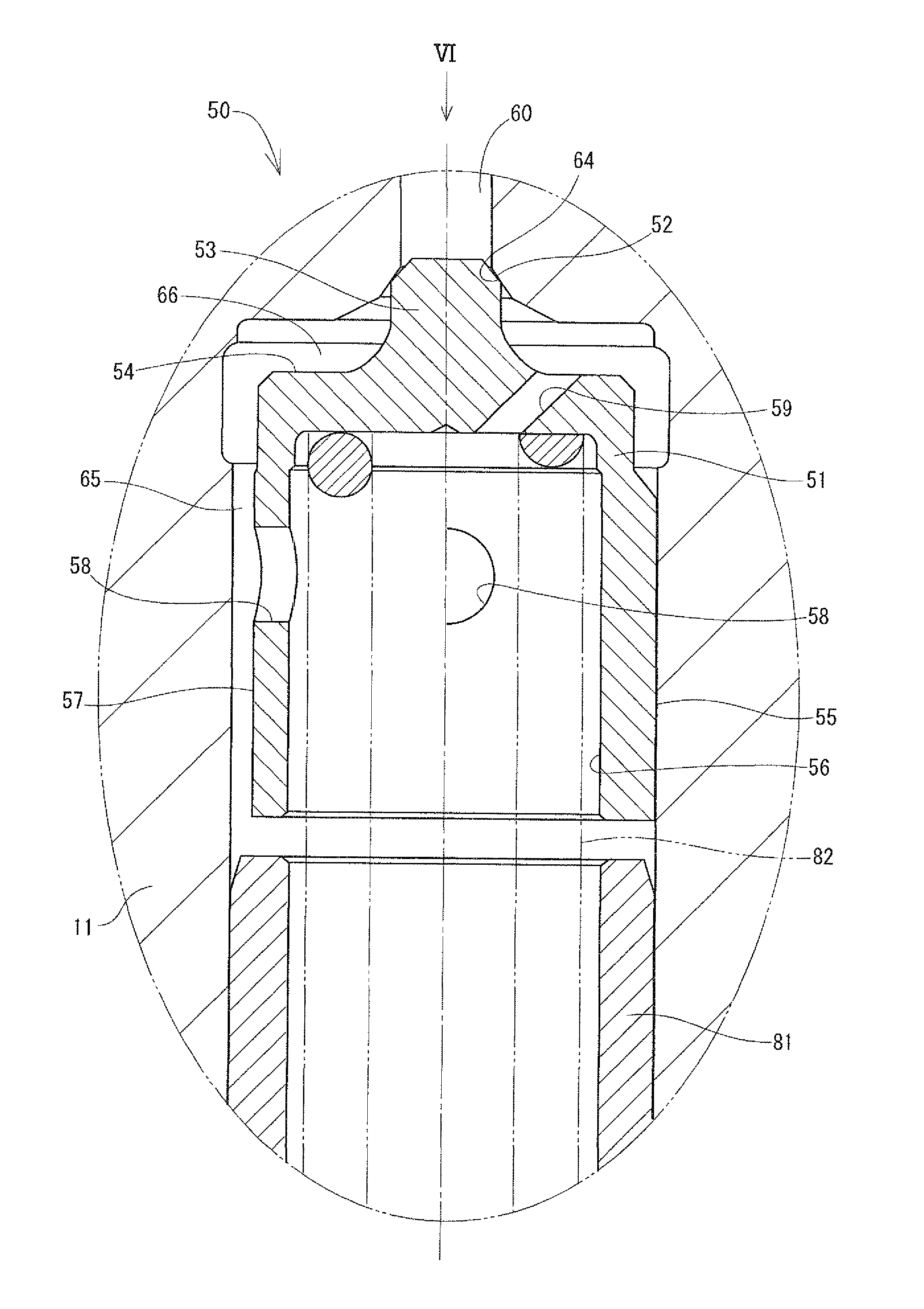
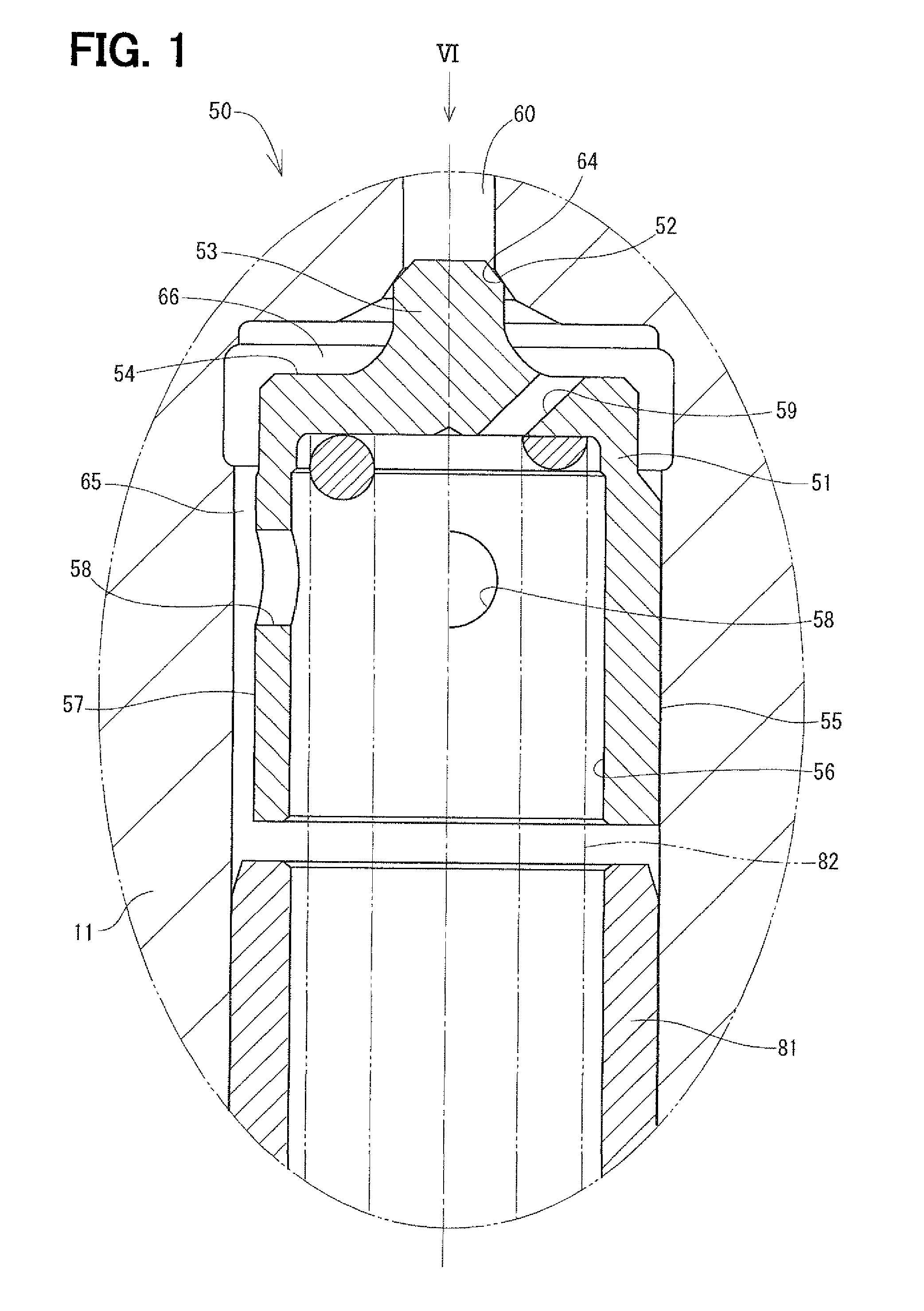
[0042]A pressure relief valve according to a first embodiment of the present invention will be explained with reference to FIGS. 1 to 8.

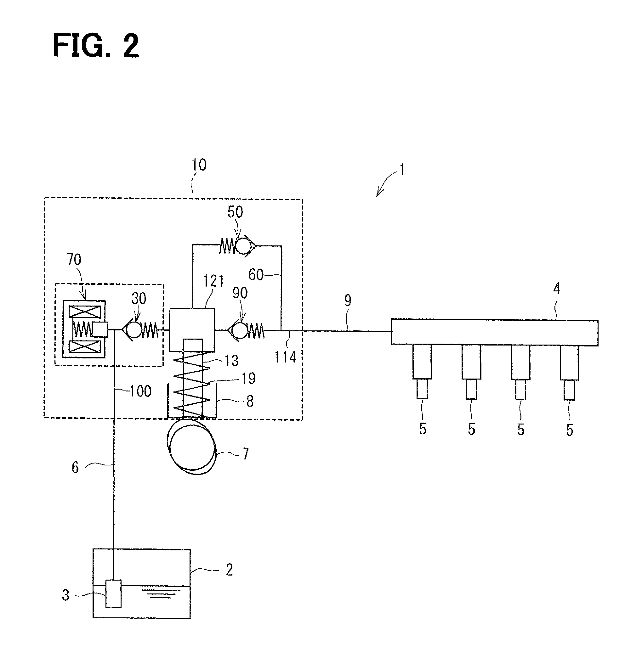
[0043]As shown in FIG. 2, the pressure relief valve 50 of the present embodiment is provided in a high pressure pump 10 used for a fuel supply system 1 of an internal combustion engine. In the fuel supply system 1, fuel drawn up by a low pressure pump 3 from a fuel tank 2 is supplied to a fuel supply passage 100 of the high pressure pump 10 via a low pressure fuel supply pipe 6. The high pressure pump 10 pressurizes the fuel, which is supplied into a fuel pressurizing chamber 121 via the fuel supply passage 100, by a reciprocal movement of a plunger 13 in its axial direction, so as to pump out the pressurized fuel via a discharge passage 114. The high pressure fuel pumped out from the discharge passage 114 is supplied to a delivery pipe 4 via a high pressure fuel supply pipe 9. The high pressure fuel is injected into respective cylinders of the inte...

second embodiment

[0116]A pressure relief valve according to a second embodiment of the present invention will be explained with reference to FIGS. 9 and 10.

[0117]According to the second embodiment, a fuel inlet port 83 of the valve member 51 is formed in a tapered shape, which has a larger cross sectional area on a side of the pressure receiving portion 54 than that on a side of the recessed portion 56. A center axis of the fuel inlet port 83 is inclined from the pressure receiving portion 54 toward the center axis of the valve member 51. An angle formed between the center axis of the fuel inlet port 83 and the pressure receiving portion 54 is an acute angle. When viewed the valve member 51 in the axial direction, as shown in FIG. 10, the fuel inlet ports 83 are formed in the valve member 51 at such portions, which are displaced from the notched portions 57 in the circumferential direction.

[0118]According to the present embodiment, since the cross sectional area of the fuel inlet port 83 on the side...

third embodiment

[0119]A pressure relief valve according to a third embodiment of the present invention will be explained with reference to FIGS. 11 and 12.

[0120]According to the present embodiment, one end of a fuel inlet port 84 is opened at the shaft portion 53 of the valve member 51, while the other end thereof is opened at the inner surface of the recessed portion 56. A center axis of the fuel inlet port 84 is inclined from the shaft portion 53 toward the center axis of the valve member 51. When viewed the valve member 51 in the axial direction, as shown in FIG. 12, the fuel inlet port 84 is formed in the valve member 51 at such a portion, which is displaced from the notched portions 57 in the circumferential direction. More exactly, a direction of the center axis of the fuel inlet port 84 is at a right angle to a line connecting the pair of the notched portions 57 with each other.

[0121]When the pressure relief valve 50 is opened, the fuel, which enters into the fuel inlet chamber 66 from the f...


PUM


Abstract

A valve member of a pressure relief valve has a shaft portion, a pressure receiving portion, and a guide portion, wherein the valve member is axially movable in a fuel return passage. When a forward end of the shaft portion is seated on a valve seta, the fuel return passage is closed, while the shaft portion is separated from the valve seat the fuel return passage is opened. A notched portion is formed at an outer wall of the guide portion to thereby form an outer-surface passage. A fuel inlet port is formed in the valve member for communicating a fuel inlet chamber to the fuel return passage at a downstream side of the valve member.

Description

CROSS REFERENCE TO RELATED APPLICATION[0001]This application is based on Japanese Patent Applications No. 2010-147695 filed on Jun. 29, 2010, and No. 2011-016967 filed on Jan. 28, 2011, the disclosures of which are incorporated herein by reference.FIELD OF THE INVENTION[0002]The present invention relates to a pressure relief valve provided in a fuel supply system for supplying fuel to an internal combustion engine and further relates to a high pressure pump using such pressure relief valve.BACKGROUND OF THE INVENTION[0003]In a conventional fuel supply system for an internal combustion engine, a high pressure pump is provided for pressurizing fuel. The fuel pressurized by the high pressure pump is supplied to a delivery pipe and accumulated therein. The high pressure fuel is then injected into respective cylinders of the engine via injectors connected to the delivery pipe.[0004]The fuel supply system and the high pressure pump are disclosed, for example, in Japanese Patent Publicatio...

Claims


Application Information

Patent Timeline
Patent Type & Authority Patents(United States)
IPC IPC(8): F02M69/54F02D41/38F16K15/00F16K15/02
CPCF02M69/54F02M63/005F04B19/22F16K15/026F02D41/3863F02M59/46Y10T137/7938Y10T137/7738Y10T137/7837
Inventor OIKAWA, SHINOBUYAMASHITA, YOSHINORIFURUTA, KATSUNORIKOBAYASHI, MASAYUKITSUGE, SHIGETO
Owner DENSO CORP
Why Eureka
Try Eureka