Circuit for communication over DC power line using high temperature electronics

a high-temperature electronics and circuit technology, applied in the field of communication over power lines, can solve the problems of extra conductors, inability to properly operate electronics, and inability to properly operate electronic components in conventional sensors and actuators

Inactive Publication Date: 2014-04-22
NASA
View PDF49 Cites 5 Cited by
  • Summary
  • Abstract
  • Description
  • Claims
  • Application Information

AI Technical Summary

Benefits of technology

[0008]Provided is a high temperature communications circuit including a power conductor for concurrently conducting electrical energy for powering circuit components and transmitting a modulated data signal, and a demodulator for demodulating the data signal and generating a serial bit stream based on the data signal. The demodulator includes an absolute value amplifier for conditionally inverting or conditionally passing a signal applied to the absolute value amplifier. The absolute value amplifier utilizes no diodes to control the conditional inversion or non-inversion of the signal applied to the absolute value amplifier.
[0009]Further provided is a high temperature communications circuit including a power conductor for concurrently conducting electrical energy for powering circuit components and transmitting a modulated data signal, and a demodulator for demodulating the data signal and generating a serial bit stream based on the data signal. The demodulator is adapted for operation in an ambient temperature of at least 200° C.

Problems solved by technology

The electronic components in conventional sensors and actuators may not operate properly under the high temperature conditions generated by such processes.
Further, environments in which it would be desirable to operate sensors and actuators that employ semiconductor electronics can experience ionizing radiation levels that are too high for the electronics to properly operate.
Extra conductors can increase system weight, cost, required space, and the risk of equipment failure.

Method used


Image

  • Circuit for communication over DC power line using high temperature electronics
  • Circuit for communication over DC power line using high temperature electronics
  • Circuit for communication over DC power line using high temperature electronics

Examples


Embodiment Construction

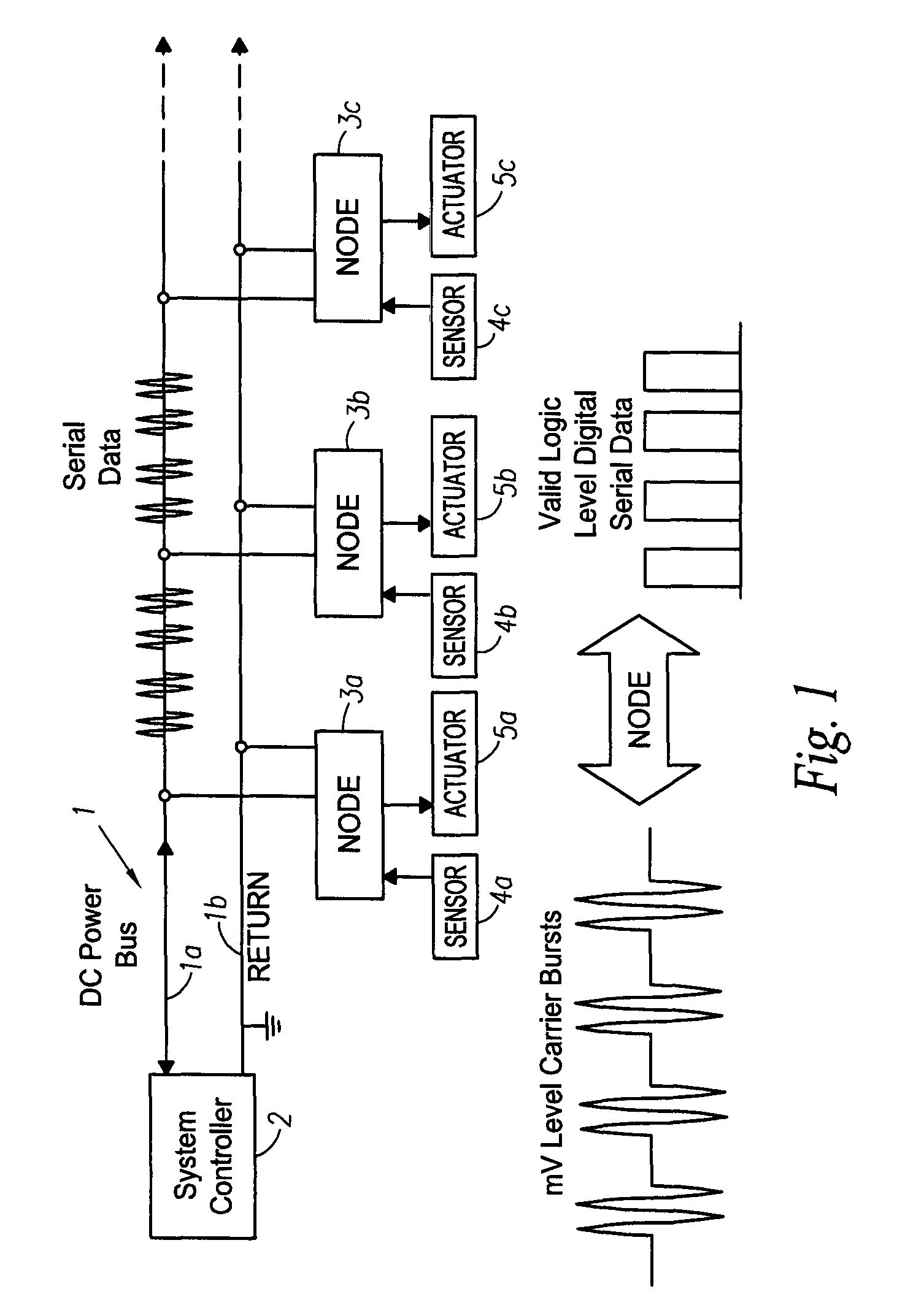
[0013]FIG. 1 shows a block diagram of a system that communicates over a power bus, for example, a direct current (DC) power bus 1. The DC power bus includes a “hot” energized line 1a and a return line 1b. DC power is supplied by a system controller 2, such as an engine controller, for example. The DC power bus 1 conducts electrical energy to one or more nodes 3a-3c, to power devices located at the nodes 3a-3c. The devices powered by the DC power bus at each node can include sensors 4a-4c and actuators 5a-5c. One or more sensors or actuators can be provided at each node 3a-3c.

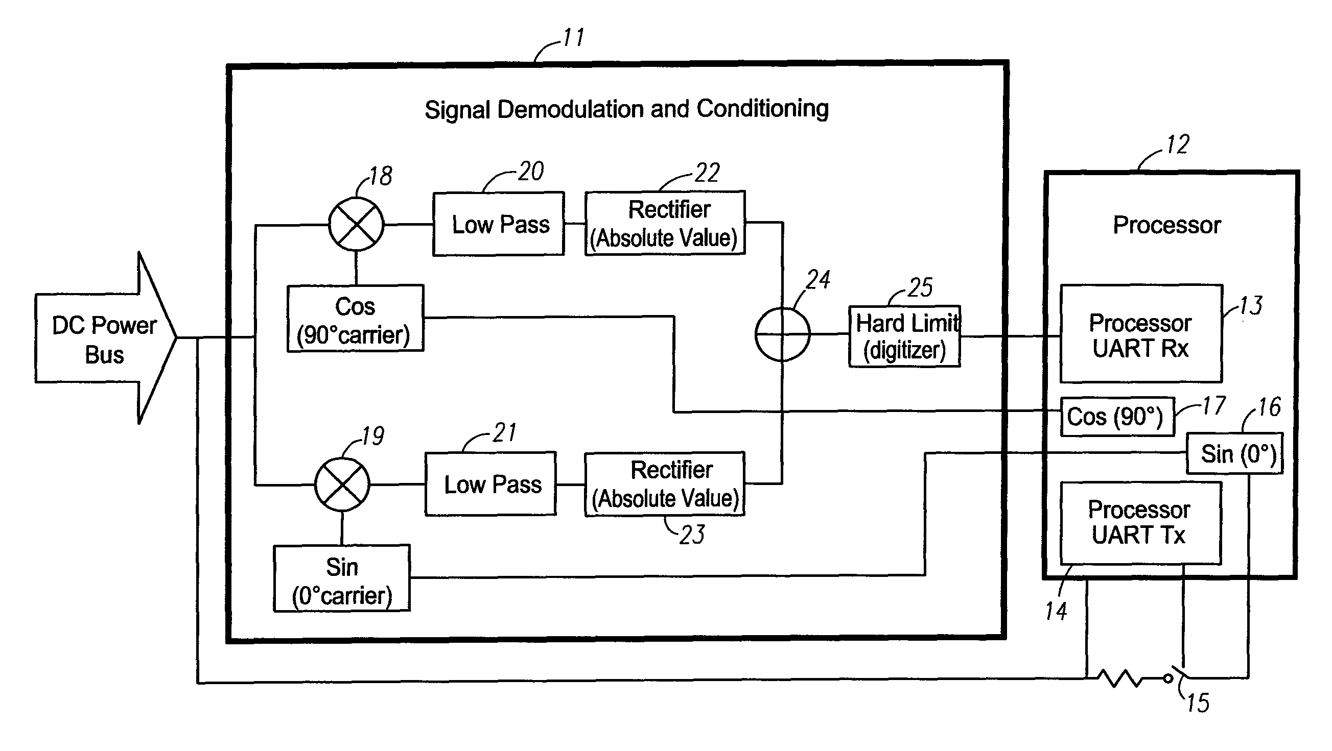
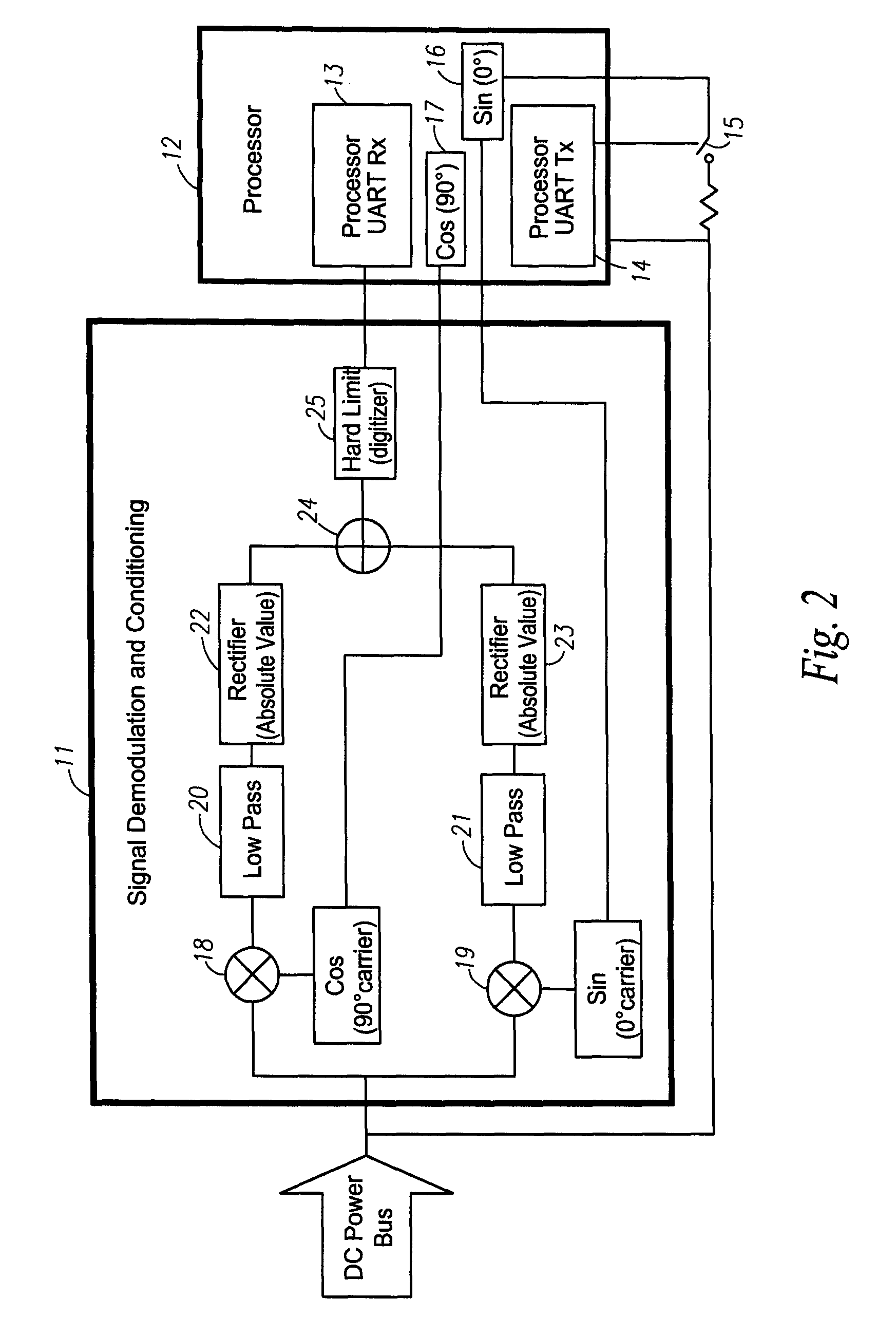
[0014]The system controller 2 generates a modulated data signal, such as an on-off-keyed data signal, which is transmitted on the DC power bus. It is to be appreciated that other types of modulated data signals besides on-off-keyed data signals could be generated by the system controller and transmitted on the DC power bus. A circuit at each node, for example, a circuit within a sensor or actuator, demodulates ...


PUM


Abstract

A high temperature communications circuit includes a power conductor for concurrently conducting electrical energy for powering circuit components and transmitting a modulated data signal, and a demodulator for demodulating the data signal and generating a serial bit stream based on the data signal. The demodulator includes an absolute value amplifier for conditionally inverting or conditionally passing a signal applied to the absolute value amplifier. The absolute value amplifier utilizes no diodes to control the conditional inversion or passing of the signal applied to the absolute value amplifier.

Description

ORIGIN OF THE INVENTION[0001]The invention described herein was made by employees of the Untied States Government and may be manufactured and used by or for the Government for Government purposes without the payment of any royalties thereon or therefore.BACKGROUND OF THE INVENTION[0002]1. Field of the Invention[0003]The present invention relates to communications over power lines, and more specifically to circuits and systems for use in high temperature environments for demodulating data signals transmitted over power lines and transmitting modulated data signals over power lines.[0004]2. Description of Related Art[0005]Environments in which it would be desirable to operate sensors and actuators that employ semiconductor electronics can have ambient temperatures that are too high for the electronics to properly operate. For example, high temperatures are generated by metal smelting or sintering processes, steel production, down hole deep drilling, and vehicle engine operation, such ...

Claims


Application Information

Patent Timeline
Patent Type & Authority Patents(United States)
IPC IPC(8): H04Q1/30H04M11/04G08B1/08
CPCH04Q1/30H04M11/04H04B2203/5475H04B3/548H04B2203/547G08B1/08
Inventor KRASOWSKI, MICHAEL J.PROKOP, NORMAN F.
Owner NASA
Why Eureka
Try Eureka