Subchannel security at the optical layer

a security layer and optical layer technology, applied in the field of optical communications, can solve the problems of affecting the security of subchannels, so as to improve data/network security. the effect of enhancing the security of data

Active Publication Date: 2014-04-22
VELLO SYST +1
View PDF162 Cites 7 Cited by
  • Summary
  • Abstract
  • Description
  • Claims
  • Application Information

AI Technical Summary

Benefits of technology

[0020]Various embodiments of the current invention are disclosed herein, including techniques, apparatus, and systems for optical WDM communications that involve dynamically modifying certain aspects of the WDM transmission (and corresponding receive) process at the optical (physical) layer to significantly enhance data / network security. Moreover, these various dynamic modifications can be employed individually or in combination to provide even greater security depending upon the desired application and design tradeoffs.
[0021]WDM transmission involves processing client signals (each received at a particular line rate of transmission) to prepare them for transmission on a fiber optic cable of an optical network. As will be discussed below, these processing steps typically include encoding the client signals, mapping them to one or more subchannels within or across ITU channels, modulating them onto subcarrier frequencies, and multiplexing them together for optical transmission. By dynamically modifying one or more of these processing steps over time (in addition to any encryption of the underlying client signals), the current invention provides additional security at the physical (optical) layer of an optical network and thus greatly enhances overall network security.
[0028]As noted above, these dynamic modifications can be employed individually or in combination to exponentially enhance the level of security by making it virtually impossible to isolate a particular client signal over time. An optical service channel (OSC) can be employed to communicate among the nodes of an optical network which of the various schemes is being employed, including the algorithms for making such modifications over time. Each node can therefore perform the appropriate modification (eg, remapping a client signal to a different subcarrier frequency) on the transmit side and, conversely, detect the modification (eg, receiving the client signal on the remapped subchannel) on the receive side.

Problems solved by technology

Installing dispersion compensation and amplifiers to compensate for their loss can be very disruptive since operators may have to break the traffic multiple times and at multiple sites.
Regardless of which embodiment is employed, however, the client traffic remains potentially vulnerable to attack.
In either case, one or more subchannel frequencies (carrying their corresponding client signals) are moved (dynamically, at various times) to a different ITU channel window, making isolation of a particular client signal over time quite difficult.
Even a shift of a few GHz could significantly impede an eavesdropper from isolating the client signal carried on a particular subchannel over time, not to mention the added complexity of tracking the signal's independent “movement” among those subchannels (or even to a different ITU channel) at different times.

Method used


Image

  • Subchannel security at the optical layer
  • Subchannel security at the optical layer
  • Subchannel security at the optical layer

Examples


Embodiment Construction

A. Alternating Scrambling / Descrambling Schemes

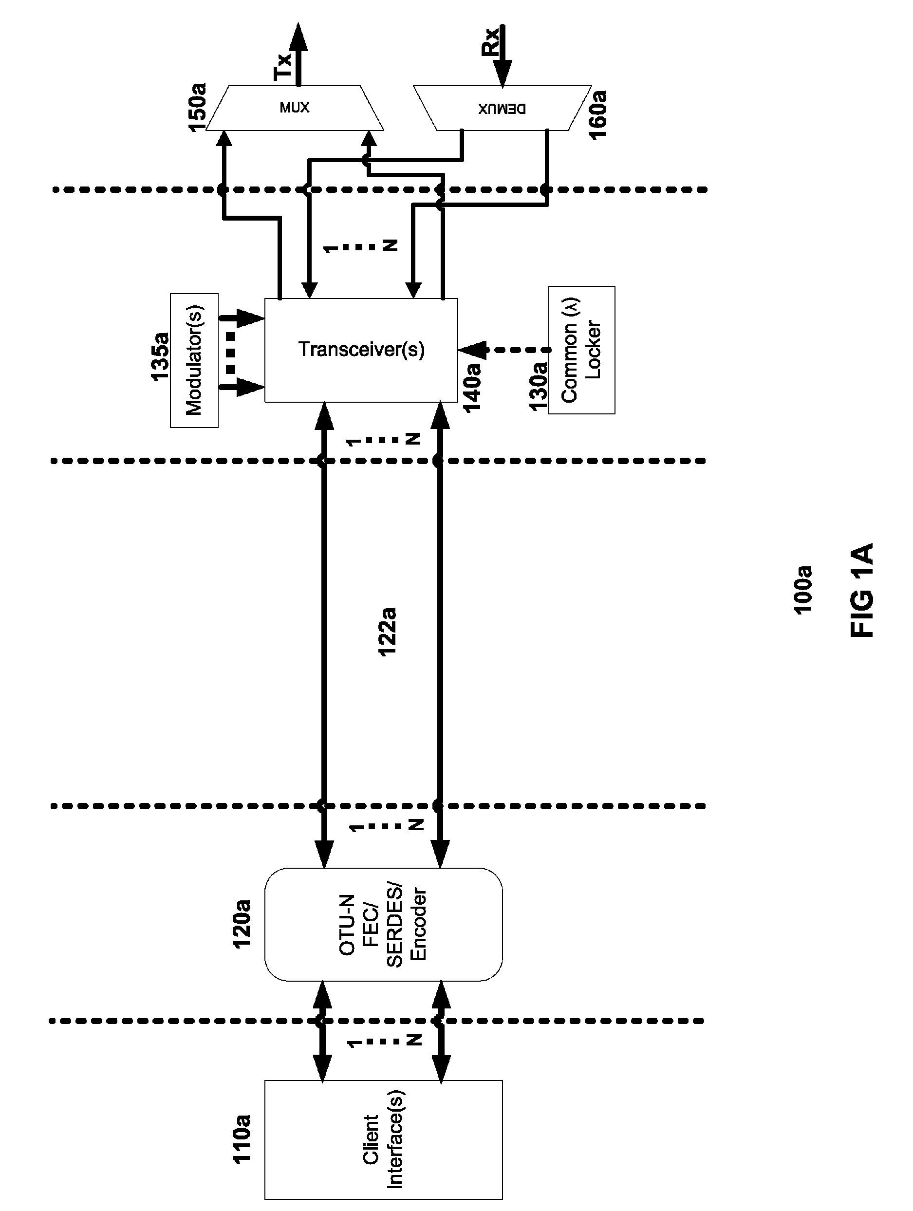
[0040]Turning to FIG. 2, subchannel muxponder 200 represents a modified embodiment of subchannel muxponder 100a of FIG. 1A, with the addition of G.709 / 975 Scrambler / Descrambler 250. As noted above, each client signal may be transmitted via any of various standard data protocols, such as Ethernet, SONET, Fibre Channel, etc. The digital processing of such client signals by FEC-SERDES block 120a of FIG. 1A involves a process of encoding each client signal into a standard frame structure for the transport of services over optical wavelengths in WDM systems. Different standard implementations of such frame structures include the G.709 and G.975 recommendations of the International Telecommunications Union (ITU-T).

[0041]In the embodiment illustrated in FIG. 2, G.709 / 975 Scrambler / Descrambler 250 causes the digital processing of client signals to alternate over time between using the G.709 standard and the G.975 standard. For example, in one em...


PUM


Abstract

The present invention includes various novel techniques, apparatus, and systems for optical WDM communications that involve dynamically modifying certain aspects of the WDM transmission (and corresponding receive) process at the optical (physical) layer to significantly enhance data / network security. These various dynamic modifications can be employed individually or in combination to provide even greater security depending upon the desired application and design tradeoffs. WDM transmission steps typically include encoding the client signals, mapping them to one or more subchannels within or across ITU channels, modulating them onto subcarrier frequencies, and multiplexing them together for optical transmission. By dynamically modifying one or more of these processing steps over time (in addition to any encryption of the underlying client signals), the current invention provides additional security at the physical (optical) layer of an optical network and thus greatly enhances overall network security.

Description

CROSS REFERENCE TO RELATED APPLICATIONS[0001]This application claims the benefit, pursuant to 35 U.S.C. §119(e), of U.S. Provisional Patent Application No. 61 / 306,925, filed Feb. 22, 2010, entitled “Subchannel Security at the Optical Layer,” which is hereby incorporated by reference in its entirety.I. BACKGROUND[0002]A. Field of Art[0003]This application relates generally to optical communications based on optical wavelength-division multiplexing (WDM), and in particular to systems and techniques for security at the optical (physical) layer of the Open Systems Interconnection (OSI) Seven Layer Model.[0004]B. Description of Related Art[0005]Optical WDM communication systems transmit multiple optical channels at different WDM carrier wavelengths through a single fiber. The infrastructures of many deployed optical fiber networks today are based on 10 Gb / s per channel. As the demand for higher transmission speeds increases, there is a need for optical networks at 40 Gb / s, 100 Gb / s or hi...

Claims


Application Information

Patent Timeline
Patent Type & Authority Patents(United States)
IPC IPC(8): H04L29/06H04B10/2581
CPCH04K1/04H04K1/10H04K1/08
Inventor VORUGANTI, PAVANMAY, KARL
Owner VELLO SYST
Why Eureka
Try Eureka