

Fast optical receiver for unencoded data
a fast optical receiver and unencoded data technology, applied in electromagnetic receivers, electromagnetic transmission, transmission monitoring, etc., can solve problems such as the change of optical loss from transmitter to receiver, and achieve the effect of improving the initialization of the receiver, reducing or no constraints on the minimum bandwidth of the signal, and improving the initial valu
- Summary
- Abstract
- Description
- Claims
- Application Information
AI Technical Summary
Benefits of technology
Problems solved by technology
Method used
Image

Examples
Embodiment Construction
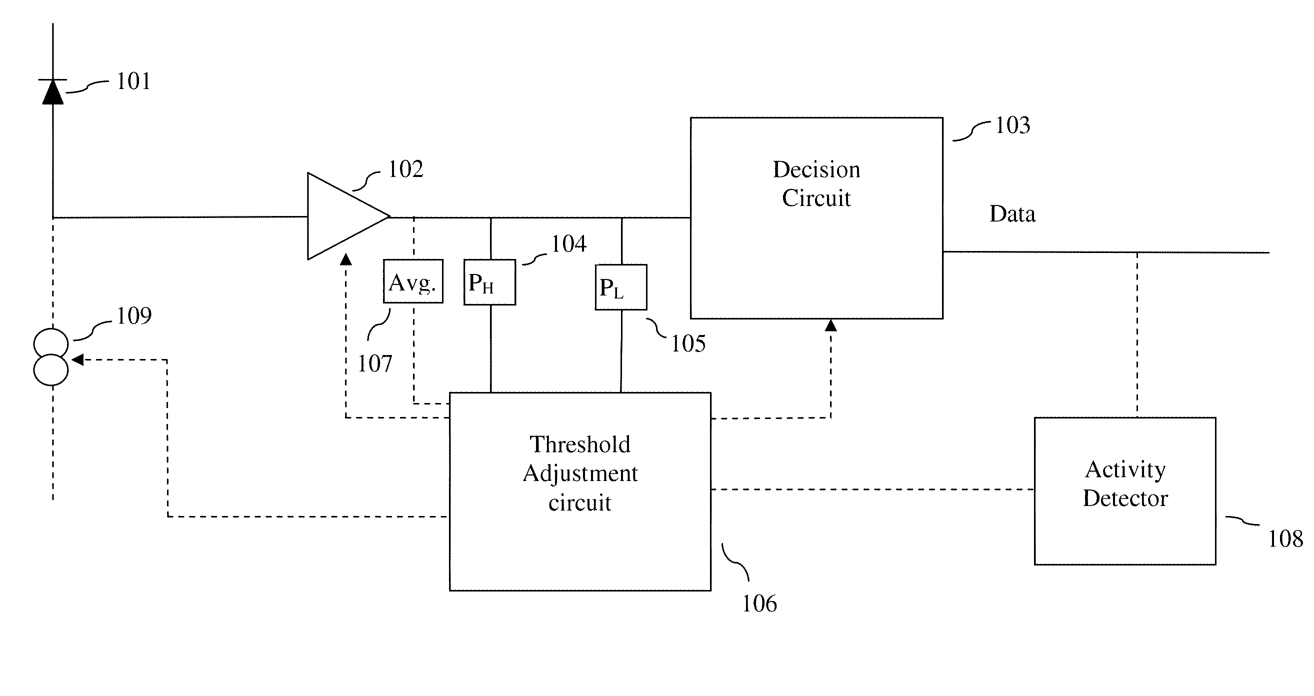
[0044]In one embodiment threshold is set to a value based in the present PH and present PL when both present PH and present PL are deemed valid. In one embodiment this has the advantage that the time span in which the extinction ratio is assumed constant may be shorter which in turn may improve accuracy in setting the threshold. In one embodiment the threshold is set as a value related to the center value between the present PH and present PL. In one embodiment the transmitter may (as an example) exhibit nonlinearity so that a DC balanced signal content does not produce a DC balanced optical signal. In one such embodiment it may be preferable to set the threshold to a value related to (PH+PL) / x where x is different from 2. In one embodiment x is determined so that the threshold is equal to the average obtained from a DC balanced signal content. In one embodiment the method comprises setting the threshold determined in the manner of the prior art receivers such as those cited above.
[...
PUM
 Abstract
Description
Claims
Application Information