
Substrate treatment system, substrate treatment method, and non-transitory computer storage medium

a technology for treating systems and substrates, applied in the direction of liquid/solution decomposition chemical coatings, superimposed coating processes, instruments, etc., can solve the problems of insufficient dry state of polyimide films, occurrence of particle contamination, and inability to function as the guide of the transfer arm, etc., to achieve the effect of appropriate treatment of substrates and suppressing the adhesion of coating films

Active Publication Date: 2014-04-29
TOKYO ELECTRON LTD
View PDF8 Cites 2 Cited by
  • Summary
  • Abstract
  • Description
  • Claims
  • Application Information

AI Technical Summary

Benefits of technology

The system effectively prevents adhesion of the coating film to the transfer arm, ensuring accurate substrate positioning and treatment, thereby reducing particle contamination and enabling reliable processing of substrates with high viscosity coatings.

Problems solved by technology

However, since the polyimide solution has a high viscosity, the dry state of the polyimide film is not sufficient yet at the time when the polyimide solution is applied in the coating treatment apparatus performing the above-described coating treatment and the wafer is then transferred out of the coating treatment apparatus.
If the polyimide film adheres to the transfer arm in this manner, the adhered matter scatters in the system or is transcribed to another wafer, causing occurrence of particle contamination.
However, in this case, the guide of the transfer arm does not function to fail to perform positioning of the wafer.
Further, for example, when the center position of the transfer arm is displaced from the center position of the wafer before transfer into the treatment apparatus, the wafer is not accurately disposed at a predetermined position in the treatment apparatus.
Therefore, it is impossible to appropriately treat the wafer in the treatment apparatus.

Method used


Image

  • Substrate treatment system, substrate treatment method, and non-transitory computer storage medium
  • Substrate treatment system, substrate treatment method, and non-transitory computer storage medium
  • Substrate treatment system, substrate treatment method, and non-transitory computer storage medium

Examples


Embodiment Construction

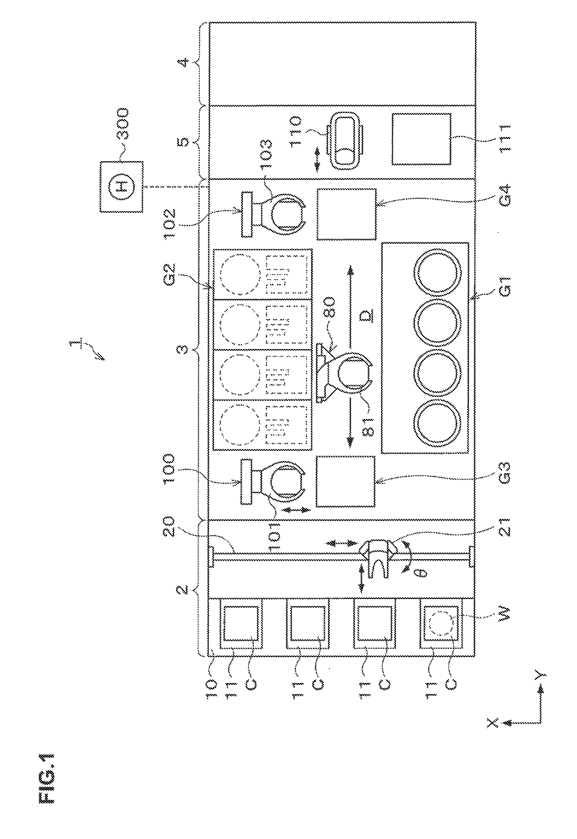
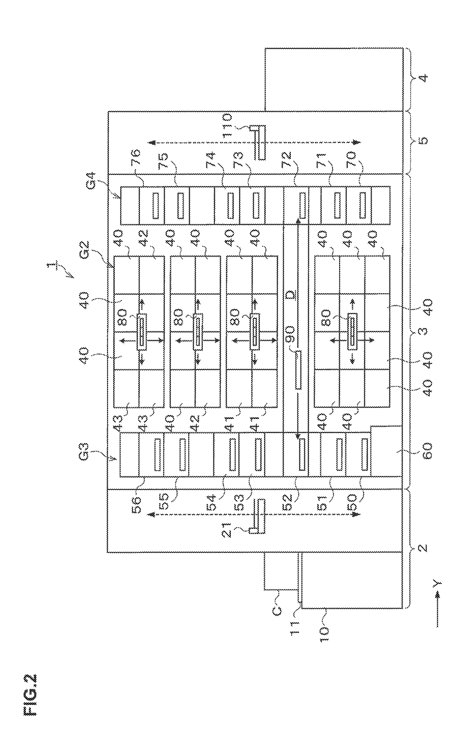
[0044]Hereinafter, an embodiment of the present invention will be described. FIG. 1 is a plan view illustrating the outline of the internal configuration of a coating and developing treatment system 1 as a substrate treatment system. FIG. 2 and FIG. 3 are side views illustrating the outline of the internal configuration of the coating and developing treatment system 1.

[0045]The coating and developing treatment system 1 has, as illustrated in FIG. 1, a configuration in which, for example, a cassette station 2 to / from which a cassette C housing a plurality of wafers W therein is transferred from / to the outside, a treatment station 3 including a plurality of various kinds of treatment apparatuses performing predetermined treatments in a manner of single wafer processing in the photolithography processing, and an interface station 5 for delivering the wafer W to / from an aligner 4 adjacent to the treatment station 3, are integrally connected together.

[0046]In the cassette station 2, a ca...


PUM

PropertyMeasurementUnit
angleaaaaaaaaaa
radius of curvatureaaaaaaaaaa
radiusaaaaaaaaaa

Abstract

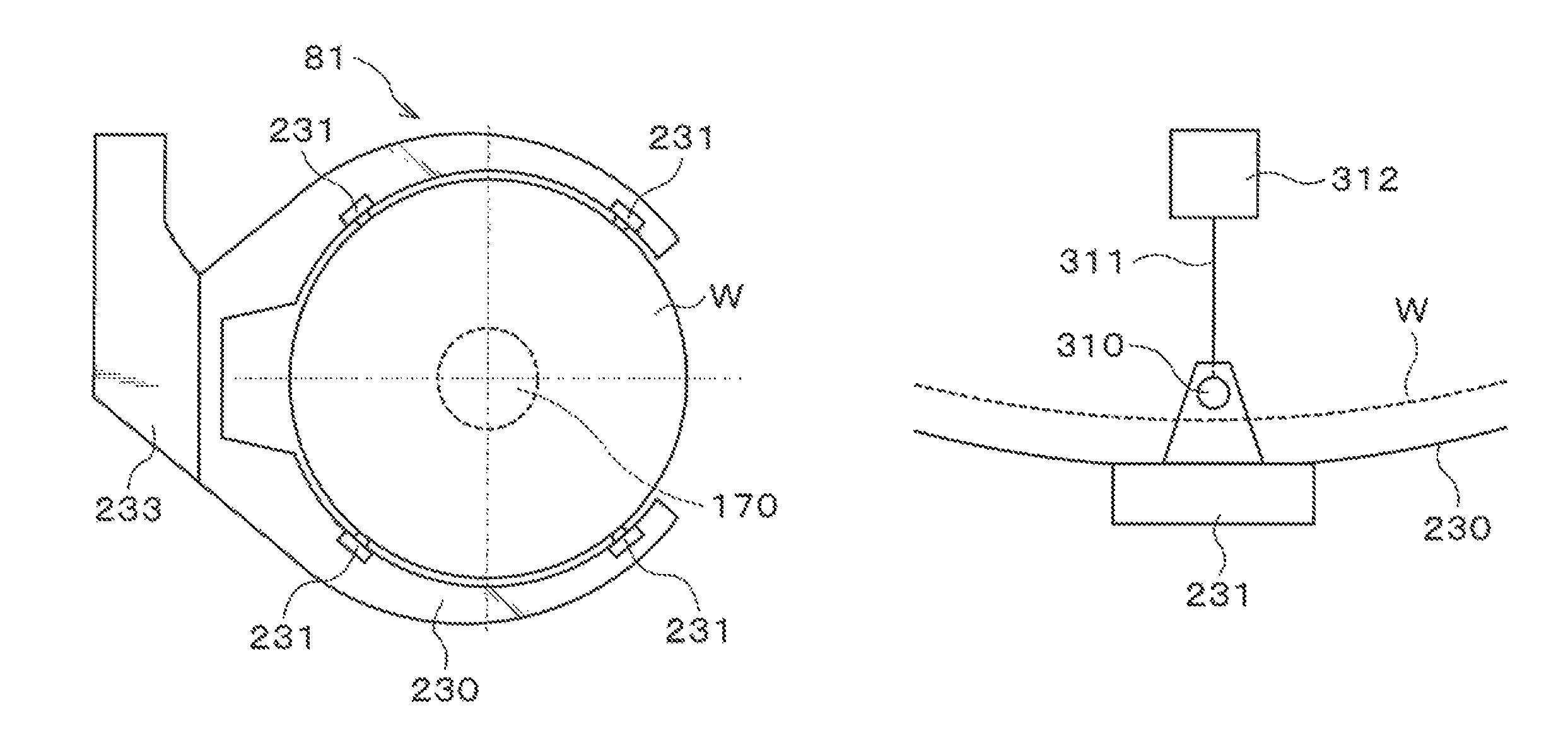
A substrate treatment system includes a plurality of treatment apparatuses, a position adjustment apparatus adjusting a center position of the substrate, a substrate transfer apparatus transferring the substrate to the treatment apparatuses and the position adjustment apparatus, and a control unit controlling operations of the apparatuses. The substrate transfer apparatus includes an arm part curved along a peripheral edge portion of the substrate with a radius of curvature larger than a radius of the substrate, and a holding part projecting inward from the arm part and holding a rear surface of the substrate. The position adjustment apparatus includes a mounting table which holds a central portion of the rear surface of the substrate and is rotatable and horizontally movable. The control unit controls the mounting table such that the center position of the substrate held on the mounting table is aligned with a center position of the arm part.

Description

BACKGROUND OF THE INVENTION[0001]1. Field of the Invention[0002]The present invention relates to a substrate treatment system, a substrate treatment method, and a non-transitory computer storage medium.[0003]2. Description of the Related Art[0004]For example, in manufacturing processes of a semiconductor device, for example, a photolithography processing is performed on a semiconductor wafer (hereinafter, referred to as a “wafer”) to form a predetermined pattern such as via holes in a polyimide film on the wafer. More specifically, coating treatment for forming the polyimide film by applying a polyimide solution onto the wafer, exposure processing for exposing a predetermined pattern on the polyimide film, developing treatment for developing the exposed polyimide film and so on are sequentially performed, whereby the predetermined pattern is formed in the polyimide film on the wafer.[0005]A series of photolithography processing is generally performed using a coating and developing t...

Claims


Application Information

Patent Timeline
Patent Type & Authority Patents(United States)
IPC IPC(8): B05C21/00B05C13/02B65H1/00B05C13/00
CPCH01L21/6719H01L21/67178H01L21/6715H01L21/67259H01L21/681H01L21/68707H01L21/6708H01L21/67017H01L21/67265H01L21/67742H01L21/6838
Inventor DEGUCHI, MASATOSHIFUNAKOSHI, HIDEOTAKEI, TOSHICHIKASATO, NORIFUMIKIYOTA, WATARUISHIMARU, DAISUKEMACHIDORI, SHINICHISUNAKA, IKUOKAMEI, SHIGENORI
Owner TOKYO ELECTRON LTD
Learn More