Liquid jet head, liquid jet apparatus, and method of manufacturing liquid jet head

a liquid jet head and liquid jet technology, applied in metal-working equipment, printing, writing implements, etc., can solve the problems of increasing the cost, small pzt substrate, and the number of pzt sheets b>103/b>, and achieve the effect of facilitating the manufacture of the liquid jet head

Active Publication Date: 2014-05-06
SII PRINTEK
View PDF15 Cites 3 Cited by
  • Summary
  • Abstract
  • Description
  • Claims
  • Application Information

AI Technical Summary

Benefits of technology

[0014]The present invention has been made in view of the above-mentioned problems with conventional methods, and an object of the present invention is to provide a liquid jet head which may eliminate the above-mentioned dead spaces so that the liquid jet head can be downsized and which may facilitate patterning of electrodes.
[0036]The liquid jet head according to the exemplary embodiment of the present invention includes: a nozzle plate including nozzles for ejecting liquid; side walls placed above the nozzle plate, the side walls forming grooves having a fixed depth in a longitudinal direction thereof; drive electrodes formed on wall surfaces of the side walls; a cover plate placed on upper surfaces of the side walls, the cover plate including: a supply port for supplying liquid to the grooves; and a discharge port for discharging liquid from the grooves; and sealing materials for closing the grooves outside communicating portions between the grooves and the supply port and between the grooves and the discharge port. In this way, the outside shape of the dicing blade in forming the grooves is not reflected, and the width in the longitudinal direction of the grooves in the liquid jet head may be set small. Further, it is not necessary to form an electrode pattern on surfaces having a height difference, which facilitates manufacture of the liquid jet head.

Problems solved by technology

Therefore, the ink jet head 100 cannot be downsized, and in addition, the number of the PZT sheets 103 obtained by dividing a PZT substrate is small, which increases the cost.
However, in the ink jet head described in Japanese Patent No. 4263742, it is necessary to form a large number of conductive tracks which are electrically separated from one another on the upper surfaces and the inclined surfaces of the PZT blocks 110 and on the upper surface of the base plate 900, and the patterning of the electrodes is complicated and processing takes a long time.
Therefore, it is difficult to collectively pattern a conductive layer deposited on the surfaces thereof by photolithography or etching and to separate the individual electrodes.
However, the number of the electrodes to be formed is several hundreds or more, and thus, it takes a very long time to pattern the electrodes.

Method used


Image

  • Liquid jet head, liquid jet apparatus, and method of manufacturing liquid jet head
  • Liquid jet head, liquid jet apparatus, and method of manufacturing liquid jet head
  • Liquid jet head, liquid jet apparatus, and method of manufacturing liquid jet head

Examples


first embodiment

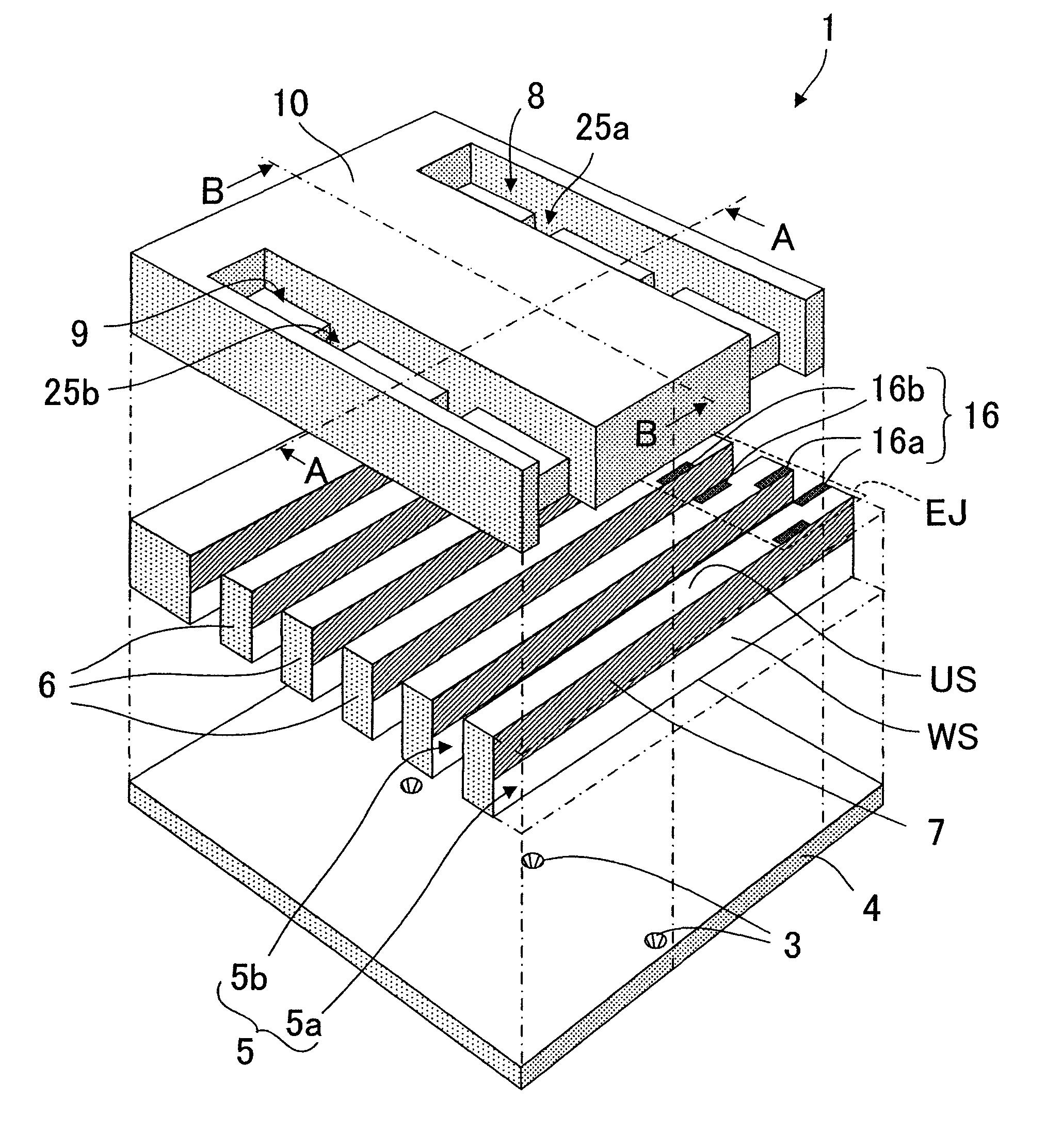
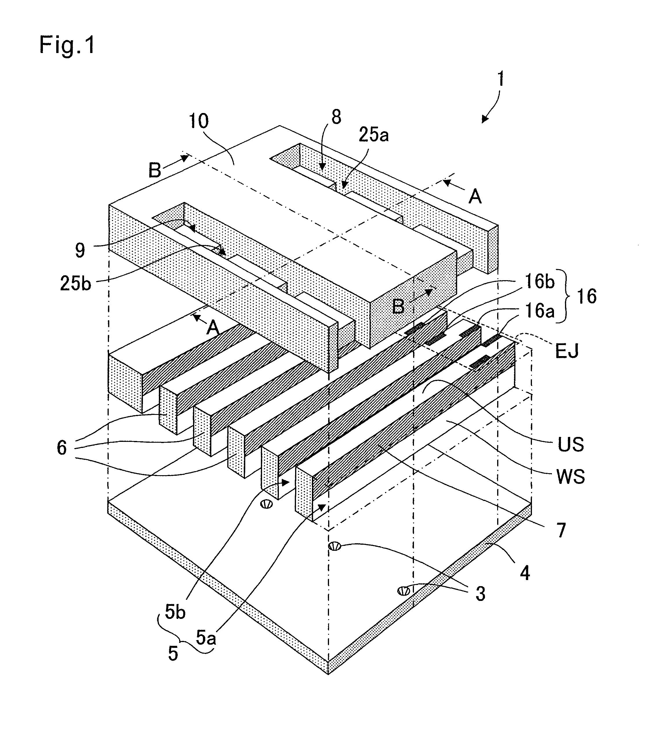
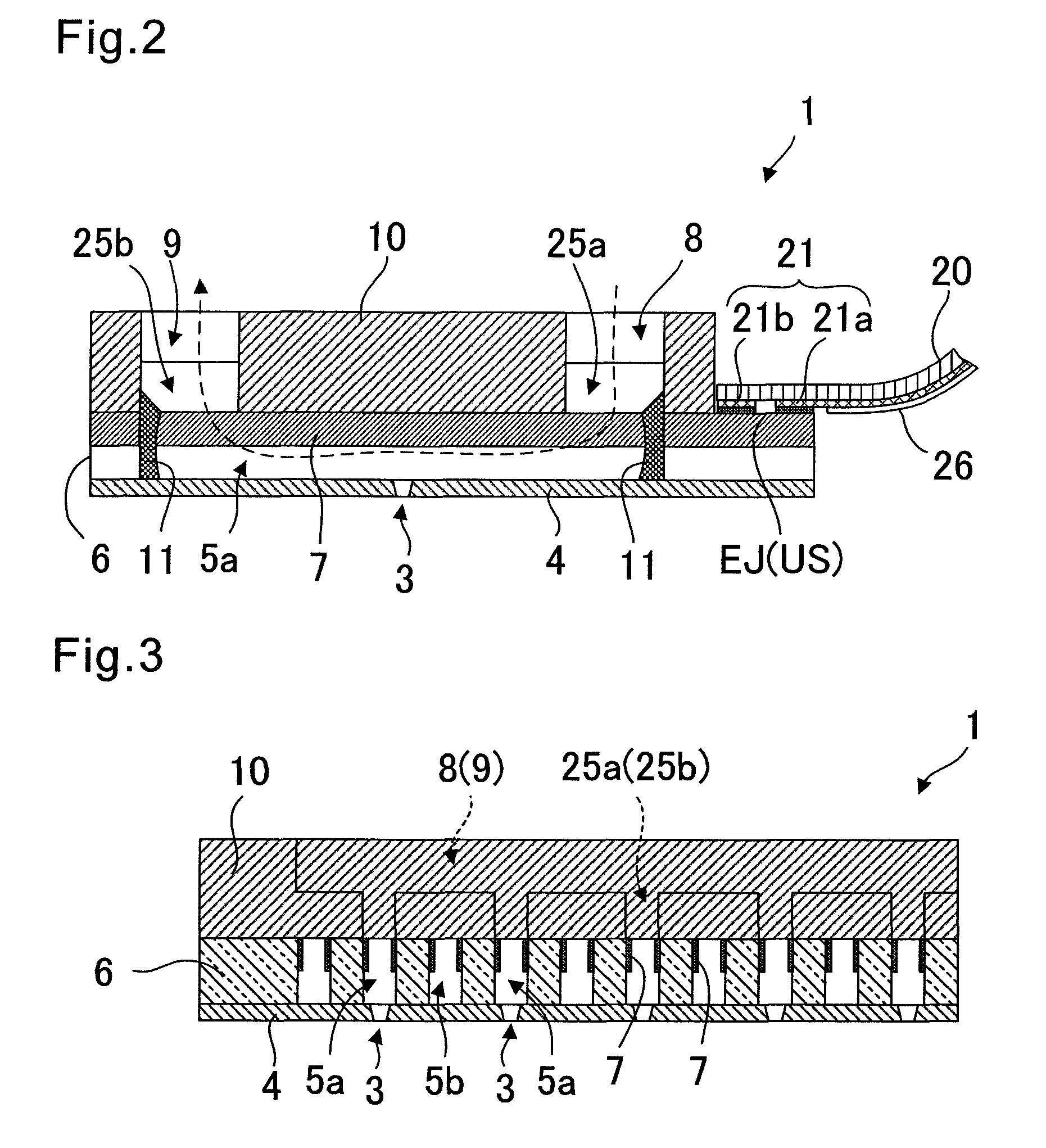
[0055]FIG. 1 is a schematic exploded perspective view of a liquid jet head according to a first embodiment of the present invention. FIG. 2 is a schematic vertical sectional view taken along the line A-A of FIG. 1. FIG. 3 is a schematic vertical sectional view taken along the line B-B of FIG. 1. Note that, in FIG. 2, a flexible substrate 20 bonded to upper surface ends EJ of side walls 6 is additionally illustrated. Further, the line A-A of FIG. 1 is located above slits 25a and 25b to be described later.

[0056]A liquid jet head 1 has a laminated structure in which a nozzle plate 4, a plurality of side walls 6 placed in parallel with one another, and a cover plate 10 are laminated. The nozzle plate 4 includes nozzles 3 for ejecting liquid therethrough. The plurality of side walls 6 are placed above the nozzle plate 4 and form a plurality of grooves 5 having a fixed depth in a longitudinal direction thereof. Each of the side walls 6 is entirely or partially formed of piezoelectric cera...

second embodiment

[0067]FIG. 4 is a schematic partial perspective view illustrating an end of a liquid jet head 1 according to a second embodiment of the present invention. FIG. 5 is a schematic partial plan view illustrating a state of connection between the extracting electrodes 16 formed on the upper surface ends EJ of the side walls 6 and the wiring electrodes 21 formed on the lower surface of the flexible substrate 20.

[0068]As illustrated in FIG. 4, the cover plate 10 is placed on the upper surfaces of the plurality of side walls 6 under a state in which the upper surface ends EJ in the longitudinal direction (y direction) of the plurality of side walls 6 are exposed. Here, it is assumed that the end side of the side walls 6 of the upper surface ends EJ is a region Ra and the cover plate 10 side of the upper surface ends EJ is a region Rb. The individual extracting electrodes 16a are formed on the end side of the upper surface ends EJ of the side walls 6 forming the dummy grooves 5b (in the regi...

third embodiment

[0073]FIGS. 6A and 6B are schematic vertical sectional views of a liquid jet head 1 according to a third embodiment of the present invention. FIG. 6A is a vertical sectional view in the longitudinal direction of the ejection groove 5a, while FIG. 6B is a vertical sectional view in a direction orthogonal to the longitudinal direction of the grooves 5. This embodiment is different from the first embodiment in that a reinforcing plate 17 is inserted between the nozzle plate 4 and the side walls 6, and is similar to the first embodiment in other respects. Therefore, in the following, points different from the first embodiment are mainly described and description of other points is omitted. Like reference symbols are used to represent like members or members having like functions.

[0074]When a drive signal is applied to the drive electrodes 7 formed on both wall surfaces WS of the side wall 6 to cause the side wall 6 to undergo thickness shear deformation, if a synthetic resin material su...


PUM

PropertyMeasurementUnit
lengthaaaaaaaaaa
depthaaaaaaaaaa
diameteraaaaaaaaaa

Abstract

A liquid jet head has a nozzle plate including nozzles for ejecting liquid and side walls placed over the nozzle plate, the side walls forming grooves having a fixed depth in a longitudinal direction thereof. Drive electrodes are formed on wall surfaces of the side walls. A cover plate is placed on upper surfaces of the side walls and has a supply port for supplying liquid to the grooves and a discharge port for discharging liquid from the grooves. Sealing materials are placed for closing the grooves outside communicating portions between the grooves and the supply port and between the grooves and the discharge port to prevent leakage of liquid from the grooves.

Description

BACKGROUND OF THE INVENTION[0001]1. Field of the Invention[0002]The present invention relates to a liquid jet head for ejecting a liquid from a nozzle to form images, characters, or a thin film material onto a recording medium. The present invention relates also to a liquid jet apparatus using the liquid jet head, and to a method of manufacturing a liquid jet head.[0003]2. Description of the Related Art[0004]In recent years, there has been used an ink-jet type liquid jet head for ejecting ink droplets on recording paper or the like to render characters or graphics thereon, or for ejecting a liquid material on a surface of an element substrate to form a functional thin film thereon. In such a liquid jet head, ink or a liquid material is supplied from a liquid tank via a supply tube to the liquid jet head, and ink or a liquid material filled into a channel is ejected from a nozzle which communicates with the channel. When ink is ejected, the liquid jet head or a recording medium on wh...

Claims


Application Information

Patent Timeline
Patent Type & Authority Patents(United States)
IPC IPC(8): B41J2/045
CPCB41J2/1632B41J2/14209B41J2/1609B41J2202/12B41J2/1634B41J2/1623B41J2/1631B41J2/045B41J2/175Y10T29/49401
Inventor KOSEKI, OSAMU
Owner SII PRINTEK
Why Eureka
Try Eureka