Heat exchanger, particularly for a motor vehicle

a technology for heat exchangers and motor vehicles, which is applied in the direction of heat exchange apparatus safety devices, machines/engines, light and heating apparatus, etc., can solve the problems of significant vibration of heat exchangers, reduce fluid flow, and ineffective heat exchange

Inactive Publication Date: 2014-05-13
BEHR GMBH & CO KG
View PDF36 Cites 4 Cited by
  • Summary
  • Abstract
  • Description
  • Claims
  • Application Information

AI Technical Summary

Benefits of technology

[0021]It is generally advantageous for the holding member to be braced against the housing. Vibrations can be avoided particularly reliably in this way, since in the end a force fit is formed between the exchanger tubes and the housing wall.
[0022]Particularly advantageously, the holding member extends at least in places in a gap between the housing and the exchanger tubes. The region between the housing and the outermost exchanger tubes is often critical in respect of an undesired flow of the second f

Problems solved by technology

Owing to mechanical vibration and the pulsed gas flow, su

Method used


Image

  • Heat exchanger, particularly for a motor vehicle
  • Heat exchanger, particularly for a motor vehicle
  • Heat exchanger, particularly for a motor vehicle

Examples


Embodiment Construction

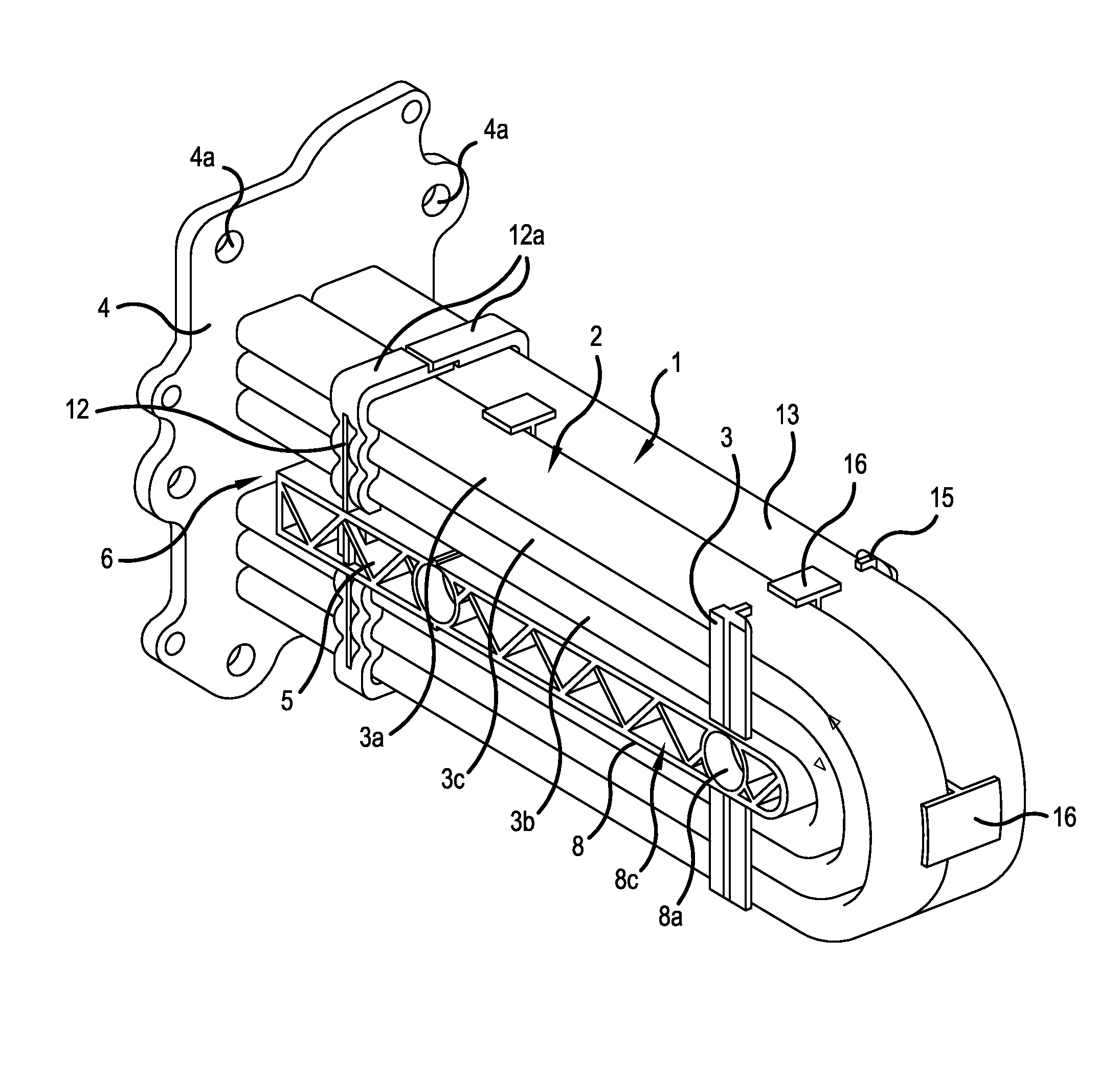
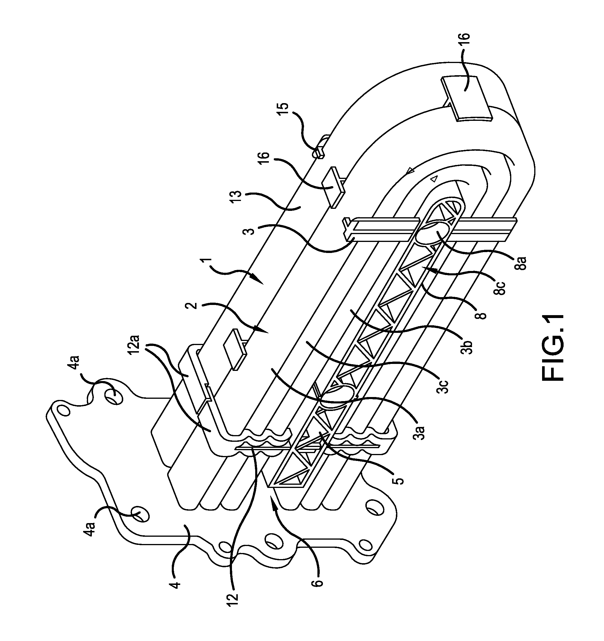
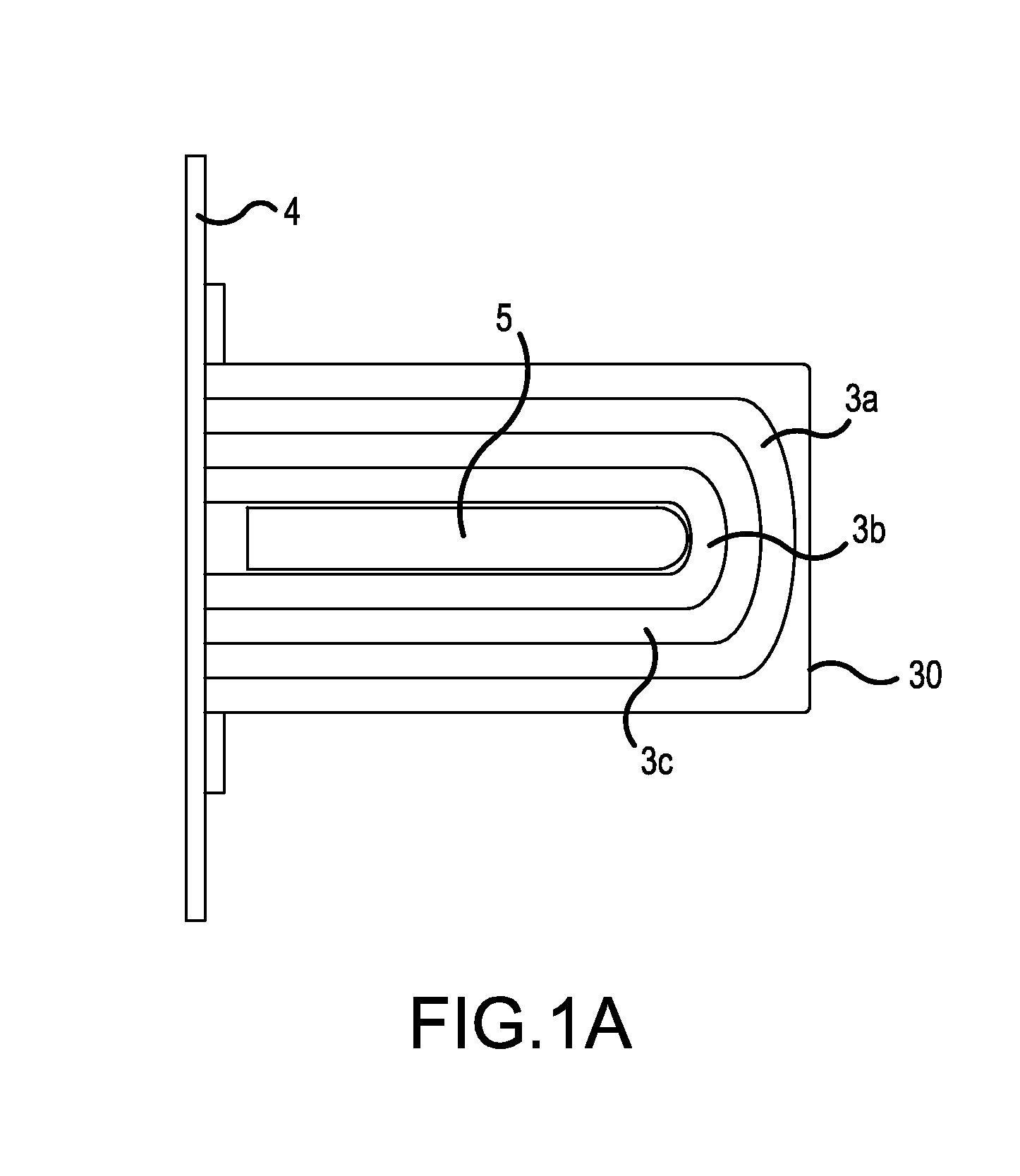
[0042]The heat exchanger according to the invention, as shown in FIG. 1, is an exhaust gas heat exchanger for the indirect liquid-cooled cooling of exhaust gas recycled for pollution abatement from a combustion engine of a motor vehicle. The heat exchanger is configured as a U-flow heat exchanger and has a first row 1 and a second row 2, parallel thereto, of exchanger tubes 3. Each of the rows 1, 2 of exchanger tubes 3 comprises three exchanger tubes bent in a U-shape and nested in one another, i.e. respectively an outer exchanger tube 3a, an inner exchanger tube with the smallest bending radius 3b and a central exchanger tube 3c extending between the two exchanger tubes 3a, 3b. In total, the heat exchanger therefore comprises six exchanger tubes respectively bent in a U-shape.

[0043]All the ends of the exchanger tubes 3 lie in a plane and open in a base 4 of the heat exchanger. In the region when they open into the base 4, they are connected by means of a local connecting method, in...


PUM


Abstract

The invention relates to a heat exchanger, particularly for a motor vehicle, comprising a plurality of exchanger tubes (3) attached to at least one floor for conveying a first fluid, wherein the exchanger tubes (3) are disposed in a housing through which a second fluid flows, wherein a holding member (5) is disposed inside the housing, wherein at least two of the exchanger tubes (3) are supported relative to one another by means of the holding member (5).

Description

BACKGROUND OF THE INVENTION[0001]The present invention relates to a heat exchanger, particularly for a motor vehicle.[0002]From the construction of heat exchangers for motor vehicles, here particularly in the field of the indirect cooling of recycled exhaust gas or charge air by a liquid coolant, tube-bundle heat exchangers are known in which a bundle of exchanger tubes, extending parallel at least in places, are fed through a housing through which a coolant flows. Owing to mechanical vibration and the pulsed gas flow, such heat exchangers are subject to significant vibrations. With a corresponding length of the exchanger tubes, strong loads due to vibration occur in the region where the tubes are fastened on a base of the heat exchanger.SUMMARY OF THE INVENTION[0003]It is an object of the invention to provide a heat exchanger which is particularly stable in respect of mechanical vibrations.[0004]For a heat exchanger as mentioned in the introduction, this object is achieved accordin...

Claims


Application Information

Patent Timeline
IPC IPC(8): F28D7/06F28F9/013
CPCF28D21/0003Y02T10/16F28F2265/30Y02T10/146F02M25/0737F28F2255/16F02B29/0462F28F9/013F28D7/06Y02T10/121F28D2021/0082F02M26/32Y02T10/12
Inventor BARWIG, JUERGENCZEMMEL, HEINZDOMES, CHRISTIANGESKES, PETERRUCKWIED, JENSSCHLEIER, GERDSPITZNAGEL, BERND
Owner BEHR GMBH & CO KG
Why Eureka
Try Eureka