
Rotary atomizing head, rotary atomization coating apparatus, and rotary atomization coating method

a technology of atomizing head and coating apparatus, which is applied in the direction of electrostatic spraying apparatus, burners, artistic surface treatment, etc., can solve the problems of inability to implement methods to reduce coating cost, affecting coating quality, and difficulty in making minute paint particles, so as to achieve desired coating efficiency, easy cleaning and removal, and improved coating quality

Inactive Publication Date: 2014-05-13
TOYOTA JIDOSHA KK +1
View PDF16 Cites 9 Cited by
  • Summary
  • Abstract
  • Description
  • Claims
  • Application Information

AI Technical Summary

Benefits of technology

The present invention is about a new apparatus and method for coating surfaces using paint sprayed by a rotary atomizing head. The invention has two main technical effects. Firstly, it allows for easy cleaning and removal of paint from the inner peripheral surface of the rotary atomizing head, which is important for maintaining its function. Secondly, it allows for the reduction of sprayed paint particles to minute particles, which improves the quality of the coating. Furthermore, the method and apparatus do not require an increase in the rotational speed of the rotary atomizing head or the pressure of the shaping air, which ensures efficient and high-quality coating. This also reduces the need for additional coating robots or increases the transfer speed, which saves on coating costs.

Problems solved by technology

This makes it difficult to make minute paint particles, which may affect the coating quality.
However, these methods to reduce the coating cost cannot be implemented without increasing the paint discharge amount from the rotary atomizing heads.
This makes it difficult to atomize the paint, thereby degrading the coating film quality.
However, increasing the rotational speed of the rotary atomizing head causes significant disturbance in the liquid ligaments 300, thereby increasing a variation in particle size distribution of atomized coating particles.
Thus, the coating efficiency is reduced if there is a large amount of coating particles in the very minute particle region, and the coating film quality is degraded if there is a large amount of coating particles in the coarse particle region.
Thus, the pressure of the shaping air needs to be increased, which increases the amount of coating particles bouncing from the surface of an object to be coated, further reducing the coating efficiency.
Thus, the rotational speed of the rotary atomizing head needs to be increased, which causes similar problems to those described above.
Thus, this coating machine provides no fundamental solution.Patent Document 1: Japanese Examined Utility Model Application Publication No.

Method used


Image

  • Rotary atomizing head, rotary atomization coating apparatus, and rotary atomization coating method
  • Rotary atomizing head, rotary atomization coating apparatus, and rotary atomization coating method
  • Rotary atomizing head, rotary atomization coating apparatus, and rotary atomization coating method

Examples


example 1

[0156]Rotary atomizing heads (outer diameter: 70 mm) according to invention 1 and invention 2 were fabricated by changing the position of the dam portion 27 provided on the inner peripheral surface 225 of the cup of the rotary atomizing head 210, and the number of paint discharge passages 229 in the rotary atomization coating apparatus of FIG. 6, as shown in FIG. 11. Then, with the rotational speed of the rotary atomizing heads being set to 25,000 rpm, atomization experiments for atomizing the paint were performed, and the particle size distribution was obtained by measuring the particle size of atomized coating particles by a particle size analyzer. Moreover, for comparison, similar atomization experiments were performed for comparative example 1 which is an existing rotary atomizing head having no dam portion 227 in the rotary atomizing head 210 of FIG. 6.

[0157]FIG. 11 herein is a table showing the total effective sectional area S of paint passages (S=the bore diameter of the pain...


PUM


Abstract

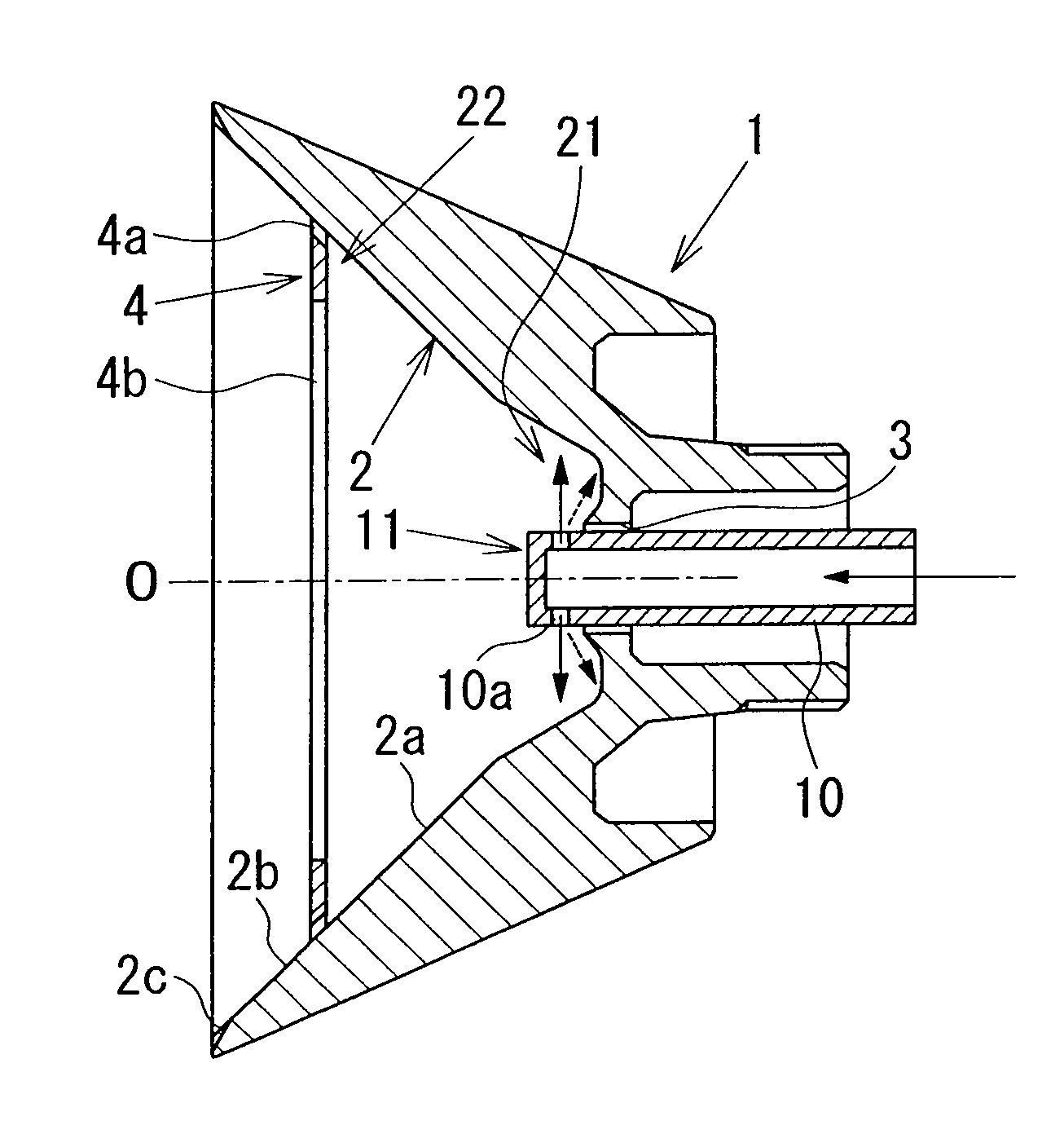
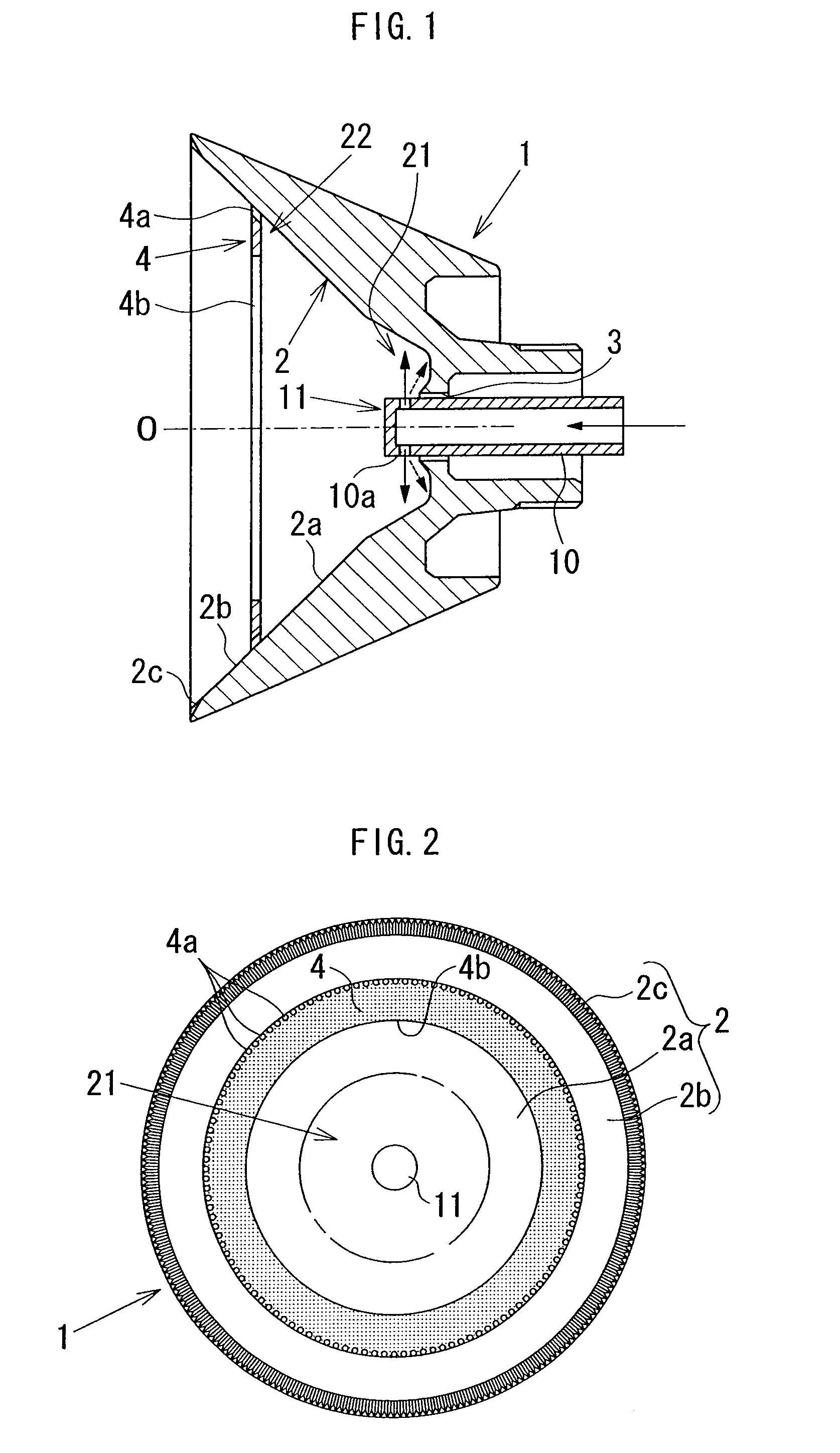
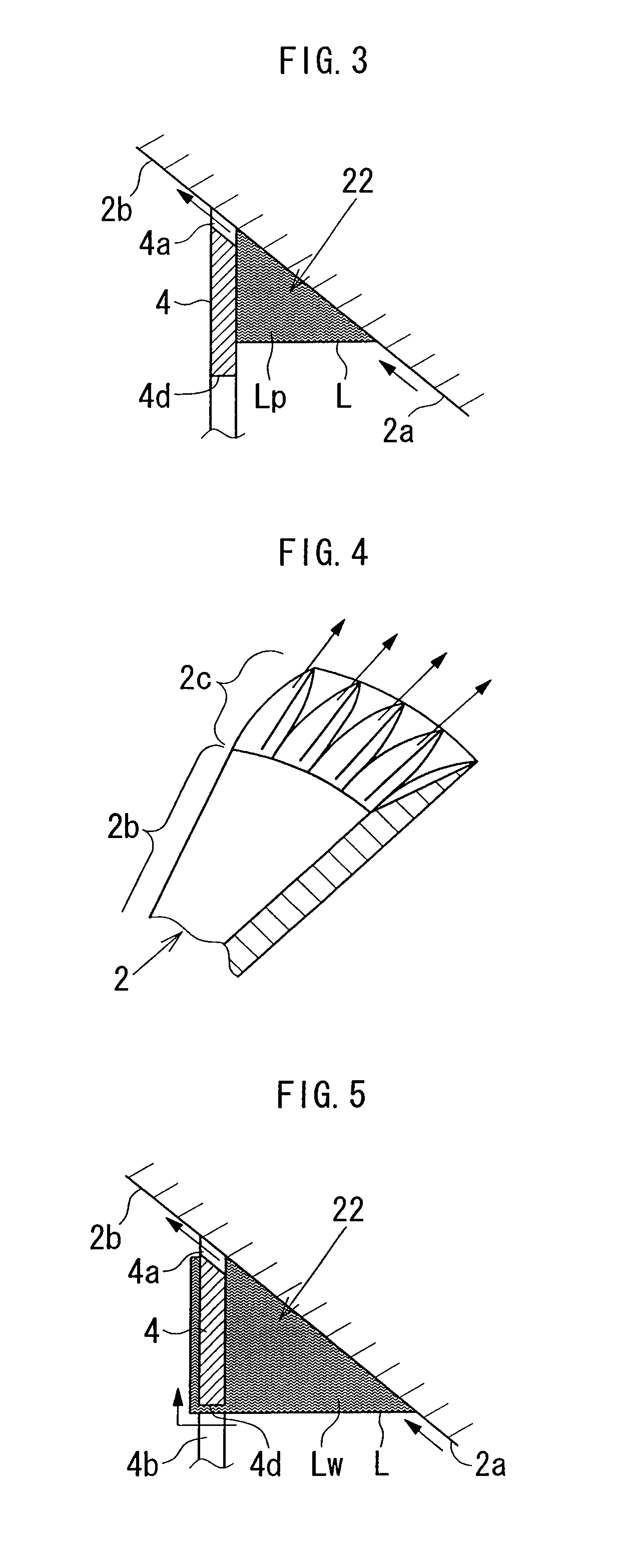
A rotary atomizing head 1, which has an inner peripheral surface 2 whose diameter increases from a bottom 21 of the inner peripheral surface toward a tip thereof, and atomizes and releases paint by applying a centrifugal force generated by rotation to the paint supplied to the bottom of the inner peripheral surface, includes a paint supply nozzle 11 for supplying the paint and a cleaning solution to the bottom of the inner peripheral surface, and the paint supply nozzle has a nozzle hole 10a for discharging the paint and the cleaning solution from a rotation center O portion of the rotary atomizing head in a direction substantially perpendicular to a rotation axis of the rotary atomizing head. The rotary atomizing head 1 also includes a dam portion 4 that is provided in an intermediate portion between the bottom and the tip of the inner peripheral surface and dams the paint and the cleaning solution supplied from the paint supply nozzle to the bottom and flow along the inner peripheral surface toward the tip.

Description

[0001]This application is a national phase application of International Application No. PCT / JP2008 / 060088, filed May 23, 2008, and claims the priority of Japanese Application Nos. 2007-138445, filed May 24, 2007, and 2007-194772, filed Jul. 26, 2007, the contents of all of which are incorporated herein by reference.TECHNICAL FIELD[0002]The present invention relates to a rotary atomizing head, rotary atomization coating apparatus, and a rotary atomization coating method for performing electrostatic coating.BACKGROUND ART[0003]A rotary atomization coating apparatus, which is conventionally known in the art, is structured so that a rotary atomizing head, which has a bell-shaped inner peripheral surface whose diameter increases from the bottom toward the tip, is rotatably mounted to a coating apparatus main body, and a centrifugal force generated by rotation is applied to paint supplied to the bottom of the inner peripheral surface of the rotary atomizing head that is rapidly rotating, ...

Claims


Application Information

Patent Timeline
Patent Type & Authority Patents(United States)
IPC IPC(8): F23D11/04B05B5/00B05B3/10B44D5/10B05B3/02
CPCB05B5/0407B05B3/1064B05B3/1014
Inventor YAMASAKI, ISAMUNABESHIMA, ATSUOMITSUI, MICHIOHOSODA, TOSHIO
Owner TOYOTA JIDOSHA KK
Learn More