System for implanting a replacement valve

a technology for implantation systems and valves, which is applied in the field of system for implanting replacement valves, can solve the problems of difficult to move through the body lumen into the implantation site, patients are exposed to all the potential dangers of major surgery, and the prosthesis that includes the venous valvular replacement and the stent is relatively bulky and thick, so as to improve the steerability of the balloon catheter, improve the accuracy of implanting the replacement valve, and improve the effect of per

Active Publication Date: 2014-05-13
MEDTRONIC INC
View PDF255 Cites 70 Cited by
  • Summary
  • Abstract
  • Description
  • Claims
  • Application Information

AI Technical Summary

Benefits of technology

[0006]A further object of the present invention is to improve the steerability of a balloon catheter used to implant a biological valve percutaneously in a patient.
[0007]A still further object of the present invention is to more accurately place a biological valve prosthesis with a desired implantation site.
[0008]Another object of the present invention is to provide a more compact system for percutaneously inserting a biological replacement valve into an implantation site.
[0009]These and other objects of the present invention are attained by a system for percutaneously inserting a biological venous valvular replacement for a defective valve within a patient through a body lumen. The system includes a balloon catheter upon which a collapsable stent containing a venous valvular replacement is mounted in a collapsed condition upon the deflated balloon. A protective shield is placed over the balloon and the replacement valve unit. The shield is movable from a closed position over the balloon to a fully opened position without having to axially displace the balloon so that the balloon can be inflated to expand the stent and accurately implant the replacement valve. A central lumen formed of a stainless steel tube passes through the catheter to provide a one to one torque ratio between the proximal end of the catheter and its distal end. The wall thickness of the venous valvular replacement is reduced from its original size by between 50% and 90% to provide for a more compact replacement package when the package is collapsed upon the uninflated balloon.

Problems solved by technology

Accordingly, the patients were exposed to all the potential dangers of major surgery.
However, the biological prosthesis that include the venous valvular replacement and the stent tends to be relatively bulky and thick even when tightly compressed against the deflated balloon and thus sometimes difficult to move through the body lumen into the implantation site.
Most catheters in present day use can not deliver the necessary torque to guide the prosthesis through the body lumen, particularly where there is a relatively tight bend in the path of travel.
In addition, most of the catheters that are equipped with protective caps do not possess the rigidity needed to hold the prosthesis in the desired location as the balloon is cleared for inflation.

Method used


Image

  • System for implanting a replacement valve
  • System for implanting a replacement valve
  • System for implanting a replacement valve

Examples


Embodiment Construction

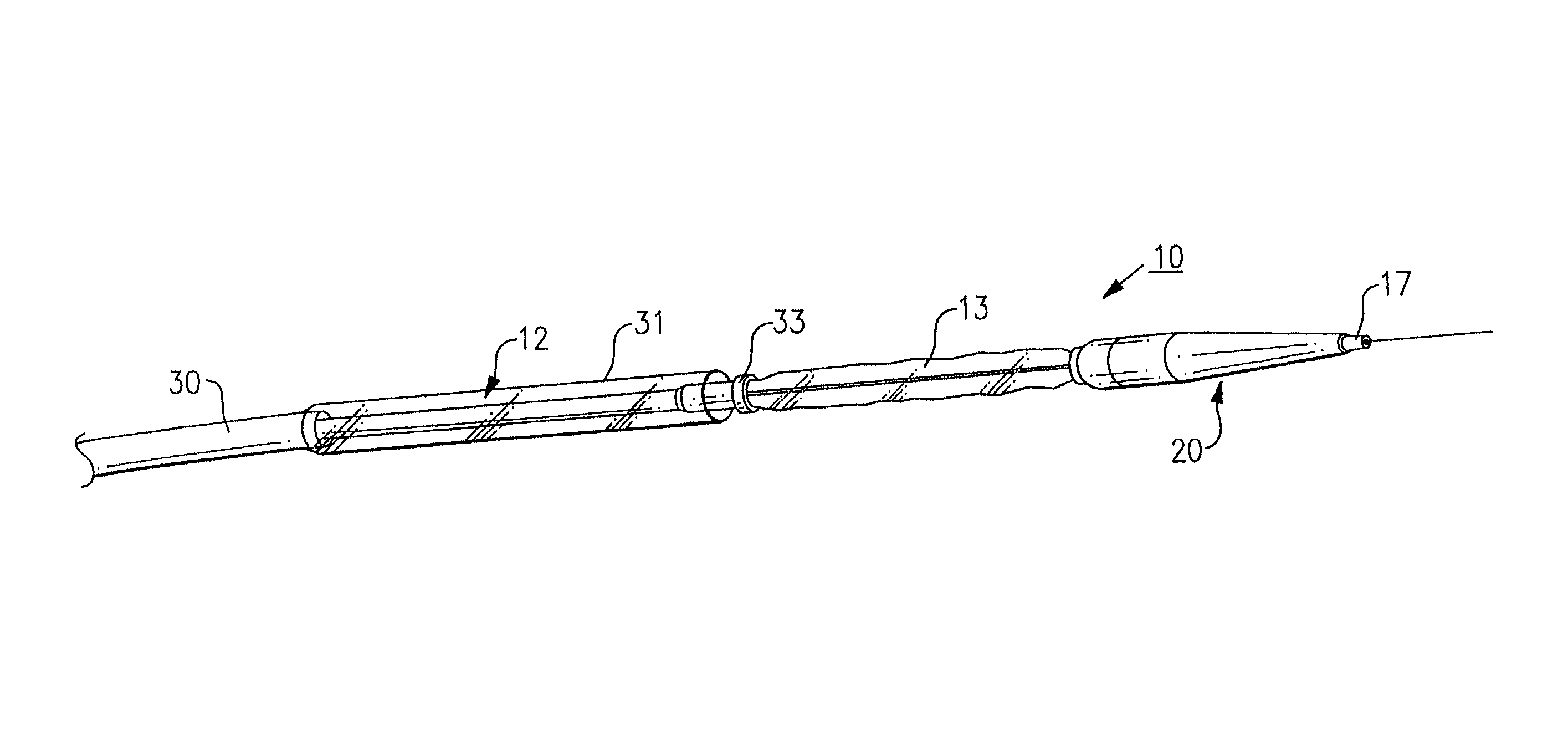
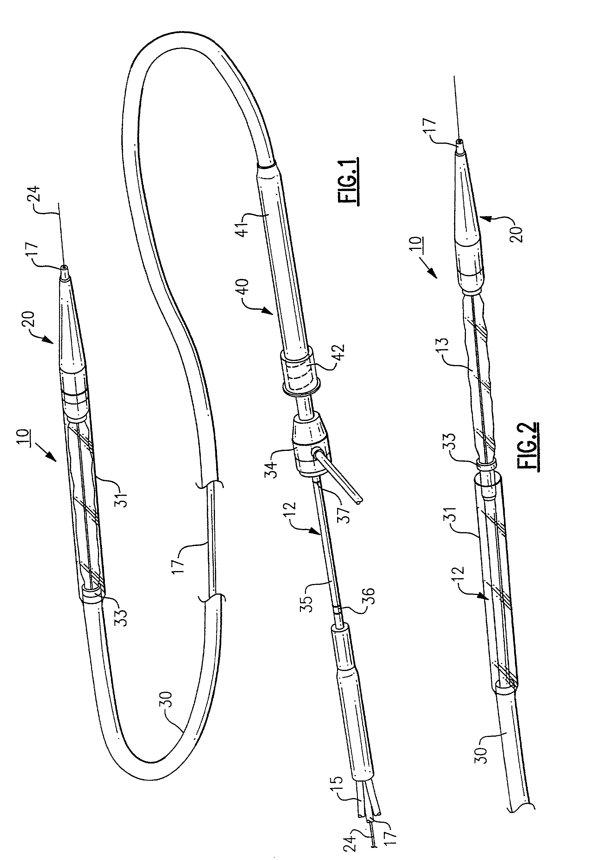
[0017]FIGS. 1 and 2 illustrate a system, generally referenced 10, for percutaneous insertion and implantation of a biological venous valvular replacement for a defective or malfunctioning valve. The system includes an elongated balloon catheter 12 having an inflatable balloon 13 joined to the distal end of the catheter. The balloon is connected in fluid flow communication with a lumen 15 through which the balloon is inflated or deflated in a manner well known in the art. Preferably the balloon is inflated using a radio-opaque fluid. Although a single balloon is shown in the present embodiment of the invention, it should be obvious to one skilled in the art that a plurality of balloons in various configurations may be employed in the practice of the present invention.

[0018]The catheter further includes a centrally located lumen 17 that passes through the entire length of the catheter from its proximal end to its distal end. The central lumen, unlike other catheter lumens employed in ...


PUM


Abstract

A system for percutaneously inserting a prosthesis containing a biological replacement for a defective valve into an implantation site through a body lumen. The system contains a balloon catheter upon which a collapsable stent containing a venous valvular replacement is mounted. A protective shield is slidably mounted upon the catheter that is movable between a closed position over the balloon and an open position wherein the balloon can be inflated to expand the stent. A central lumen runs through the catheter that is formed of stainless steel. The central lumen provides a one to one torque ratio between the proximal end of the catheter and the distal end to enhance the steerability of the catheter. The vein of the replacement is reduced in thickness between 50% and 90% of its original size thereby considerably reducing the size of the replacement package when the stem is collapsed upon the balloon of the catheter.

Description

FIELD OF THE INVENTION[0001]This invention relates to a system for the percutaneous implantation of a biological venous valvular replacement for a human valve.BACKGROUND OF THE INVENTION[0002]There exists a need in the medical field for an improved system for carrying out the percutaneous implantation of biological venous valvular replacements for human valves and in particular cardiac valves. Up until recently, many valves such as heart valves had to be replaced surgically. Accordingly, the patients were exposed to all the potential dangers of major surgery.[0003]Recently, procedures have been devised for implanting biological valves harvested from animals percutaneously into humans to replace damaged or malfunctioning valves. Andersen et al. in U.S. Pat. No. 5,840,081 describes a system for carrying out such a procedure. In Andersen et al., a biological cardiac valve is mounted upon the expandable stent of a catheter. The assembly is crimped onto the balloon section of the cathete...

Claims


Application Information

Patent Timeline
Patent Type & Authority Patents(United States)
IPC IPC(8): A61M25/01A61F2/24A61F2/90
CPCA61F2/90A61F2/2475A61F2/958A61F2/2412A61F2/2433
Inventor TOWER, ALLEN J.BONHOEFFER, PHILIPPMARTIN, MICHAEL L.
Owner MEDTRONIC INC
Why Eureka
Try Eureka