Device for positioning a plate element in an infeed station of a processing machine

a technology for processing machines and plate elements, applied in the field of devices, can solve the problems of limiting the possible rate of running the plate elements in the machine, forming a fairly damaged zone of the plate element, and affecting the processing efficiency of the machin

Active Publication Date: 2014-05-20
BOBST MEX SA
View PDF23 Cites 30 Cited by
  • Summary
  • Abstract
  • Description
  • Claims
  • Application Information

AI Technical Summary

Benefits of technology

[0021]A main object of the present invention consists in developing a device for positioning a plate element in an infeed station of a machine for treating the element. A second object is to build a positioning device that is particularly simple to build and implement and is not very costly. A third object is to fit an infeed station with a device for positioning an element that requires only a minimum of modifications to operate accurately and quickly. Yet another object is to provide a machine for treating a plate element, allowing the subsequent conveyor to grip the element correctly aligned, thanks to an infeed station and a positioning device, and to bring it into the stations to be treated effectively.
[0026]According to one aspect of the present invention, the motor is able to move the holding device from the upstream position to various downstream positions, as a function of the signal emitted by the detection device, so as to bring this element from the rear position to the intermediate position.
[0032]Longitudinal positioning is achieved in an accurate and sufficient manner, thanks to a single motor for moving the temporary holding device. Frontal jogging with its lays is eliminated. The signal emitted by the detection device is used to calculate an instantaneous rear position of the element, a position that is then compared with a reference position. This signal then allows bringing the element from the rear position to the chosen intermediate position.

Problems solved by technology

This substantially limits the possible rate for running the plate elements in the machine.
In addition, pressing a plate element against a lay causes formation of a zone of the plate element that is fairly damaged, and visible on the corresponding edge.
This damaged zone causes jams of the plate elements in the machine.
Changes in format, in this case in the length of the plate element, require a change of the cam, which is incompatible with current requirements to reduce adjustment times as much as possible for the profitability of the machine.
In this prior document, it is not possible to obtain a variation or a longitudinal adjustment of the position of the shelf and therefore of the plate element.
In the event of incorrect longitudinal placement of the plate element, the shelf cannot make a correction.
Moreover, no means is provided or described in the prior document for detecting, without contact, the front edge of the plate element.
The plate elements are therefore damaged because of their frontal jogging.
The jogging of such a cardboard may cause the bottom sheet to be damaged over a length and / or to fold up or down or against the front edge of the cardboard.
Moreover, with a plate element of laminated corrugated cardboard, the starting reference frame corresponding to the rear longitudinal position is lost or is very imprecise, when the plate element is positioned against a starting gauge or when it comes up against a lay, because of the flexibility of the laminated bottom sheet.
The positioning of the plate element gripped by the conveyor therefore becomes imprecise, making for imprecise treating by the machine.

Method used


Image

  • Device for positioning a plate element in an infeed station of a processing machine
  • Device for positioning a plate element in an infeed station of a processing machine

Examples


first embodiment

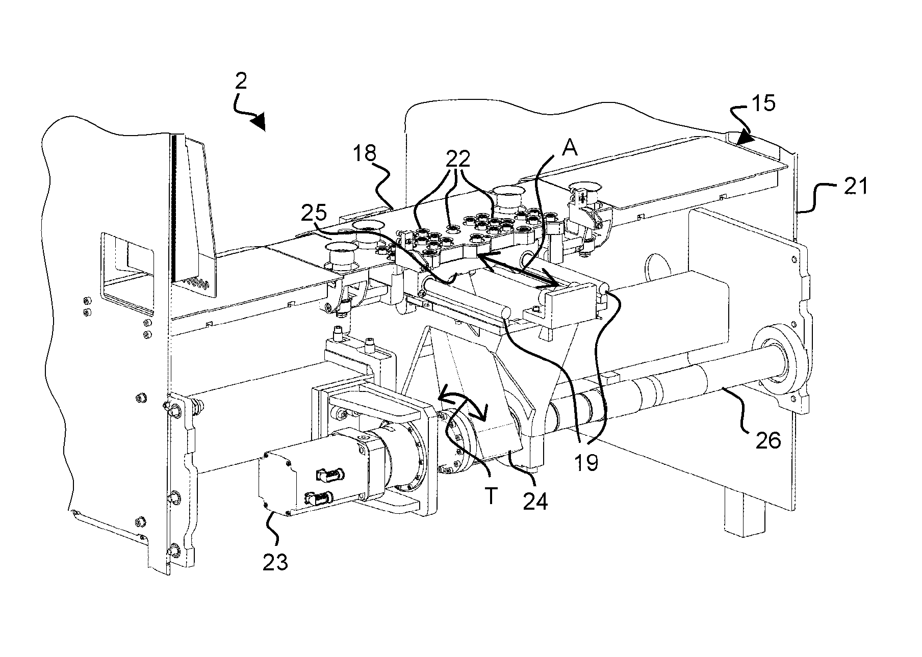
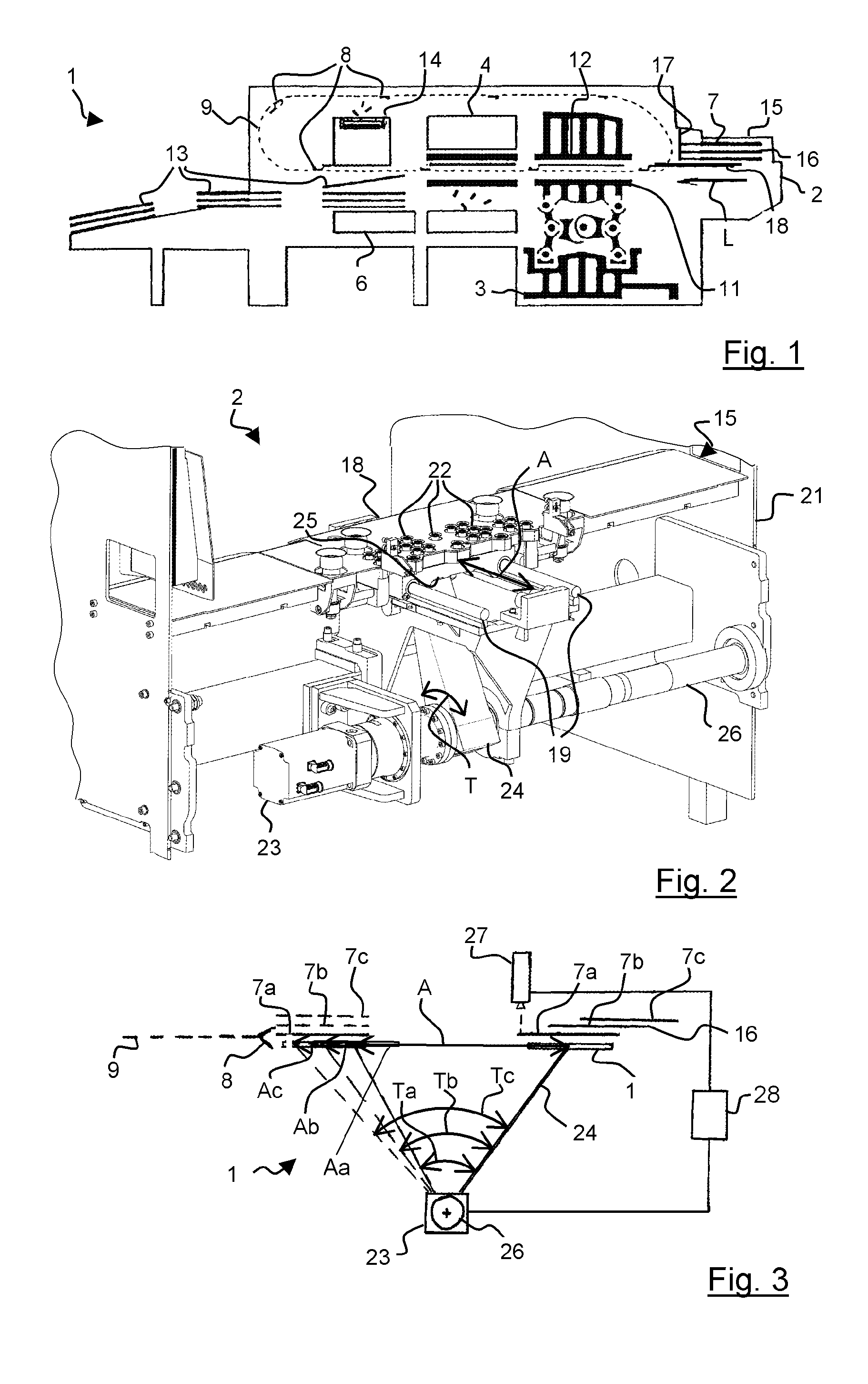
[0046]In a first embodiment and advantageously, the infeed device (18) may be in the form of a shelf that can move longitudinally (A). The shelf can favorably slide longitudinally (A) on two lower longitudinal slides (19) mounted on a frame (21).

[0047]In a first variant of the first embodiment, the shelf (18) may have suction holes (22) connected to a vacuum source (not shown), to pick up the sheets to be cut (7) by their lower face. Means for controlling vacuum suction are also provided to release the sheet to be cut (7) at the accurate moment when the gripper bar (8) grips it.

[0048]The positioning device (15) then comprises a motor (23) moving the infeed device (18) longitudinally (A) from the upstream position to the downstream position, and vice-versa, depending on the rated running of the press (1). The motor (23) of the infeed device (18) is positionally slaved according to the rated running of the gripper bar chains (9) of the press (1), usually detected by the angle of the o...

second embodiment

[0058]In a second embodiment, the temporary holding means for the sheets to be cut (7) may be in the form of a vacuum conveyor with endless belts driven by the motor, for example substantially similar to those described in the document EP-0,501,213. These types of temporary holding means comprise a suction chamber with one face perforated by many suction holes and which is connected to a vacuum source such as a vacuum suction pump. A set of endless conveyor bands or belts are guided and driven by pulleys located at the front and rear ends of the chamber and pass along the perforated face of the chamber to return to the opposite face.

[0059]The motor controlled according to the invention drives one of the end pulleys. The sheets to be cut (7) are thus laid by suction against the endless belts and then brought at an accurate intermediate position to be gripped there by the gripper bar (8). The distance of movement of the sheets to be cut (7) is a function of their starting longitudinal...

third embodiment

[0060]In a third embodiment, the temporary holding means for the sheets to be cut (7) may be in the form of a vacuum conveyor with rollers driven by the motor, for example substantially similar to those described in the document EP-0.363.662. These types of temporary holding means comprise a frame constituted with two beams connected together by a series of crossmembers. These side beams support, in integrated bearings, a series of shafts parallel with one another at right angles to the direction of movement of the sheets to be cut (7). These shafts have a series of drive rollers carved from the block. A plate covers the lower face of the frame, except at rectangular openings through which the lower portion of the rollers passes, which thus emerge from the plate.

[0061]The motor controlled according to the invention drives the shafts and thus the rollers. The sheets to be cut (7) are thus laid by suction against the rollers, and then brought at an accurate intermediate position to be...


PUM


Abstract

A device for positioning a plate element (7a, 7b, 7c) in an infeed station (2) of a machine for treating the element (1), fitted with a conveyor (8, 9), gripping the element (7a, 7b, 7c) which is found in a predetermined intermediate position, and carrying the element (7a, 7b, 7c) in a rated running into successive processing stations (3, 4, 6). The device includes a holding device (18) for temporarily holding the element (7a, 7b, 7c), the holding device moving longitudinally alternatively (A) from an upstream position to a downstream position, and vice-versa, to pick up the element (7a, 7b, 7c) in a rear position and bring it to the intermediate position, and to return empty. A motor (23) moves the holding device (18) longitudinally, from the upstream position to the downstream position, and vice-versa, as a function of the rated running. A detector (27) detects a rear longitudinal position in which the element (7a, 7b, 7c) is found, and emits a position signal. The motor (23) is able to move (A, Aa, Ab, Ac) the holding device (18) from the upstream position to various downstream positions, as a function of the signal emitted by the detection device (27), so as to bring the element (7a, 7b, 7c) from the rear position to the intermediate position.

Description

CROSS-REFERENCE TO RELATED APPLICATIONS[0001]The present application is a 35 U.S.C. §§371 national phase conversion of PCT / EP2010 / 000170, filed Jan. 14, 2010 which claims priority of European Application No. 09001392.1, filed Feb. 2, 2009, the contents of which are incorporated by reference herein. The PCT International Application was published in the French language.[0002]The present invention relates to a device for positioning a plate element in an infeed station. The invention also relates to an infeed station comprising such a device for positioning a plate element. The invention also concerns a processing machine incorporating such an infeed station.[0003]A processing machine, for example a converting machine for cutting on a platen, is used notably in the printing and packaging industry, for example for making cardboard boxes from plate elements such as sheets.[0004]The plate elements are taken from a stack situated upstream of the machine and are picked up by a feeder in an...

Claims


Application Information

Patent Timeline
Patent Type & Authority Patents(United States)
IPC IPC(8): B65H3/24B65H9/14B65H1/08
CPCB65H5/10B65H2511/20B65H2801/42B65H9/105B65H2511/222B65H2220/03B65H2220/02B65H9/10
Inventor CHIARI, MAUROLAMBELET, RAYMOND
Owner BOBST MEX SA
Why Eureka
Try Eureka