
Switching regulator control circuit and switching regulator

a technology of switching regulator and control circuit, which is applied in the direction of power conversion systems, dc-dc conversion, instruments, etc., can solve the problems of difficult to obtain a voltage absolute value with high accuracy and relatively easy to obtain a ratio with high accuracy, and suppress manufacturing fluctuations of duty of detection. , the effect of high accuracy

Inactive Publication Date: 2014-05-20
ABLIC INC
View PDF11 Cites 0 Cited by
  • Summary
  • Abstract
  • Description
  • Claims
  • Application Information

AI Technical Summary

Benefits of technology

The present invention provides a switching regulator control circuit with an overload protection circuit. The circuit uses a rate-based method to determine the duty of overload detection in PWM control. This method helps to accurately detect overload conditions and minimize manufacturing fluctuations. This eliminates the need for post-correction steps and improves the overall performance of the circuit.

Problems solved by technology

It is well-known that, in a semiconductor integrated circuit, obtaining a voltage absolute value with high accuracy is difficult in many cases, but obtaining the ratio with high accuracy is relatively easy.

Method used


Image

  • Switching regulator control circuit and switching regulator
  • Switching regulator control circuit and switching regulator
  • Switching regulator control circuit and switching regulator

Examples


Embodiment Construction

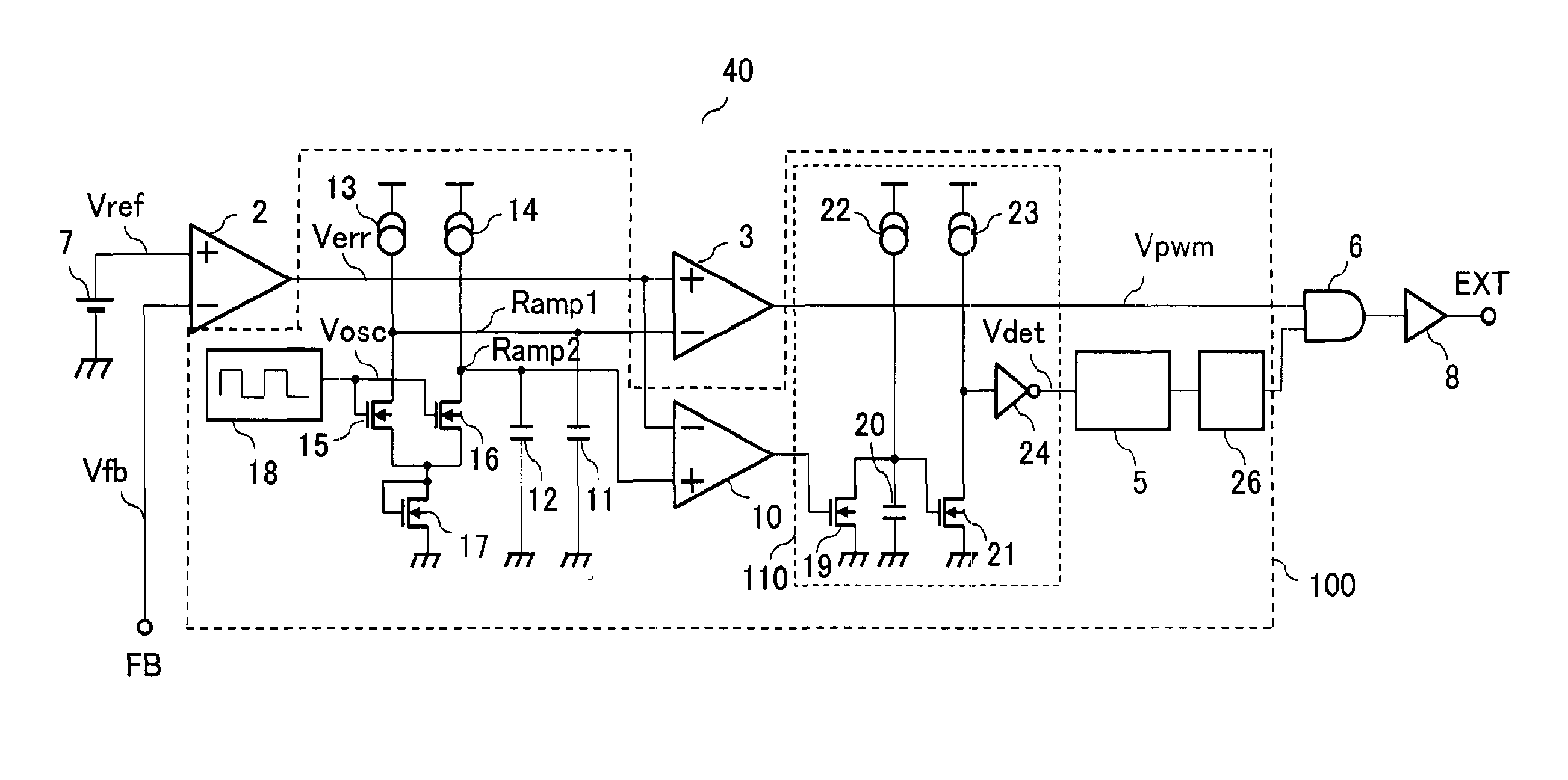
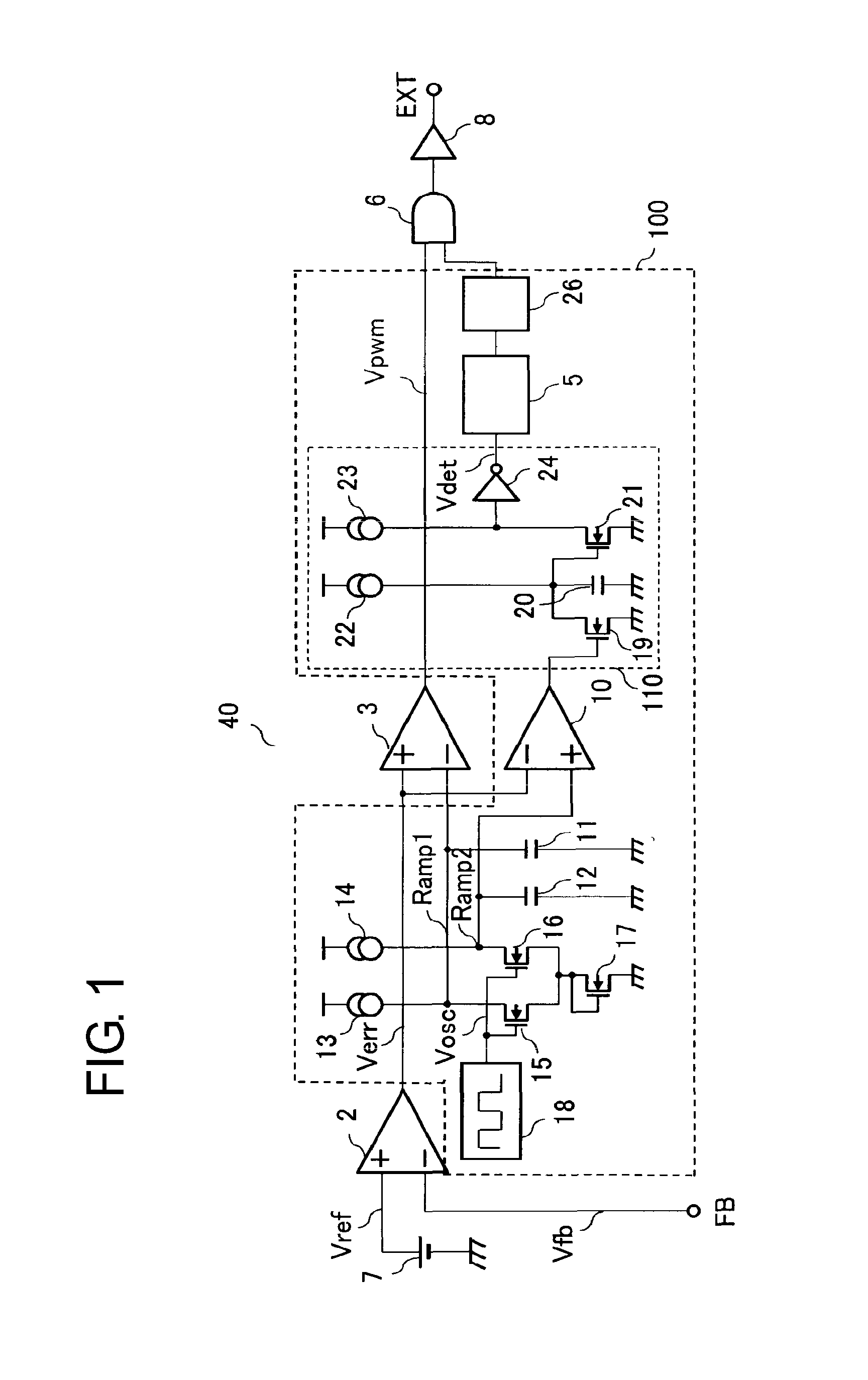
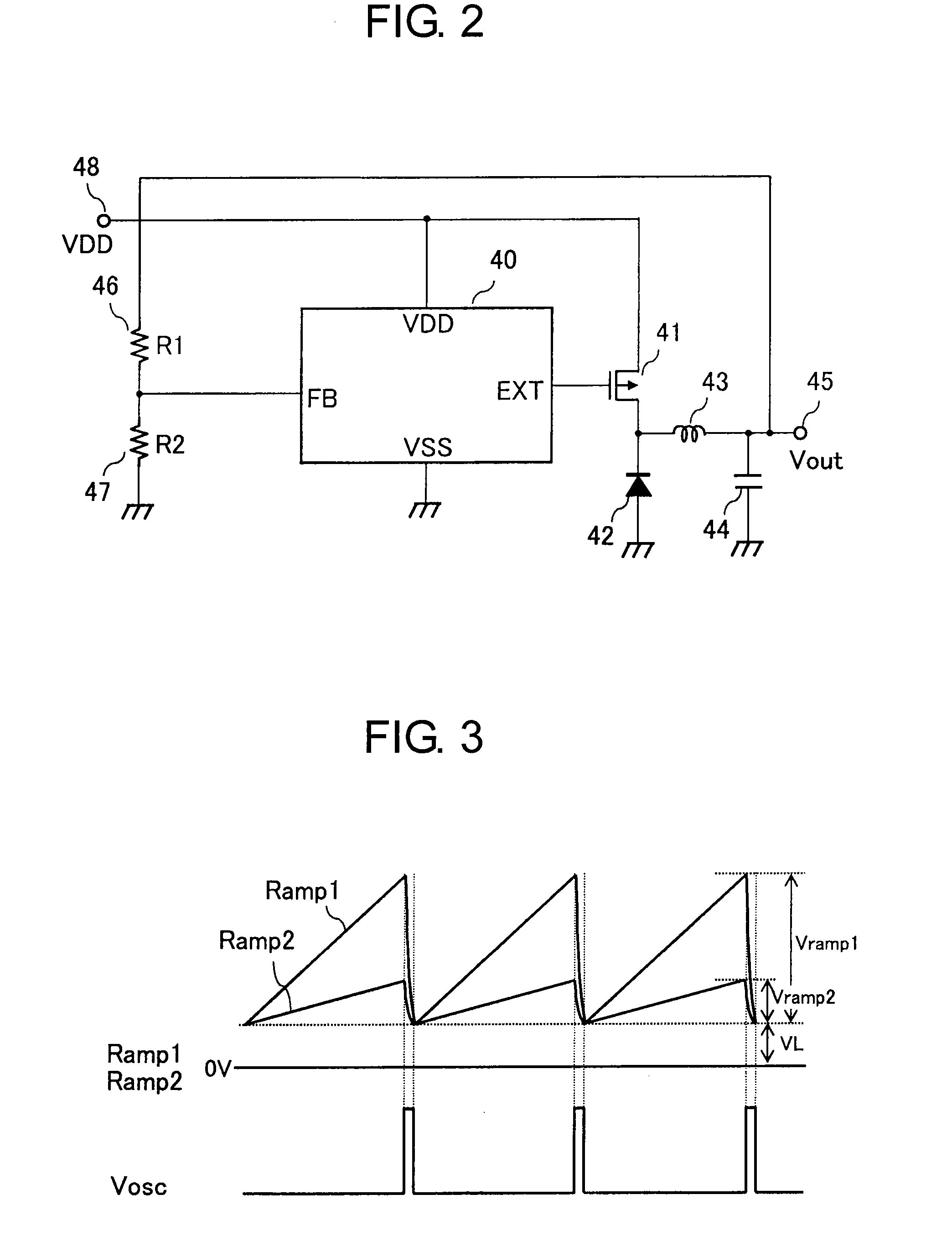
[0024]FIG. 1 is a block diagram of a switching regulator control circuit including an overload protection circuit according to an embodiment of the present invention. FIG. 2 is a block diagram illustrating an example of a switching regulator including the switching regulator control circuit according to this embodiment. As an example, the block diagram of FIG. 2 illustrates a step-down switching regulator.

[0025]The switching regulator illustrated in FIG. 2 includes a switching regulator control circuit 40, a driver transistor 41, a diode 42, a coil 43, an output capacitor 44, output voltage dividing resistors 46 and 47, a power supply terminal 48, and an output terminal 45.

[0026]The switching regulator control circuit 40 illustrated in FIG. 1 includes an error amplifier 2, a reference voltage circuit 7, a rectangular wave oscillation circuit 18, a first triangle wave (Ramp1) generation circuit, a first comparator 3, an overload protection circuit 100, a gate circuit 6, and a buffer ...


PUM


Abstract

Provided is a switching regulator including an overload protection circuit, which has high accuracy even without requiring adjusting means in a test step. The switching regulator includes: a first triangle wave generation circuit for generating a first triangle wave which controls Duty of a PWM signal; and a second triangle wave generation circuit for generating a second triangle wave for overload detection, which has a crest value smaller than that of the first triangle wave. A ratio between the crest value of the first triangle wave and the crest value of the second triangle wave is set based on respective capacitances or constant currents thereof.

Description

RELATED APPLICATIONS[0001]This application claims priority under 35 U.S.C. §119 to Japanese Patent Application No. 2011-019640 filed on Feb. 1, 2011, the entire content of which is hereby incorporated by reference.BACKGROUND OF THE INVENTION[0002]1. Field of the Invention[0003]The present invention relates to a switching regulator for outputting a constant voltage, and more particularly, to an overload protection circuit for interrupting current supply to an output to protect a circuit when an overcurrent flows to an output terminal.[0004]2. Description of the Related Art[0005]Switching regulators are used as voltage supply sources of various electronic device circuits. The switching regulator functions so as to output a constant voltage to an output terminal regardless of voltage fluctuations of an input terminal. In addition, the switching regulator also has an important function of overload protection performed by interrupting current supply for protection of a circuit when a cur...

Claims


Application Information

Patent Timeline
Patent Type & Authority Patents(United States)
IPC IPC(8): G05F1/40
CPCH02M1/32H02M3/156G05F1/569
Inventor DEGUCHI, MICHIYASU
Owner ABLIC INC
Learn More