Image display apparatus and image display method

a technology of image display and apparatus, applied in the field of image display apparatus and image display method, can solve the problem of difficult to efficiently observe the three-dimensional distribution of abnormal shadows (candidates) when a plurality of abnormal shadows is present, and achieve the effect of efficient observation

Inactive Publication Date: 2014-05-20
CANON KK
View PDF23 Cites 13 Cited by
  • Summary
  • Abstract
  • Description
  • Claims
  • Application Information

AI Technical Summary

Benefits of technology

[0011]With the image display apparatus according to the present invention, display of a plurality of cross sectional images can be simultaneously switched in parallel according to a display switch parameter set for each coordinate axis. It has an advantage of enabling efficient observation of a three-dimensional distribution of a plurality of positions of interest.

Problems solved by technology

With these conventional techniques of displaying three cross sectional images, however, it is difficult to efficiently observe the three-dimensional distribution of abnormal shadows (candidates) when a plurality of abnormal shadows exist.

Method used


Image

  • Image display apparatus and image display method
  • Image display apparatus and image display method
  • Image display apparatus and image display method

Examples


first embodiment

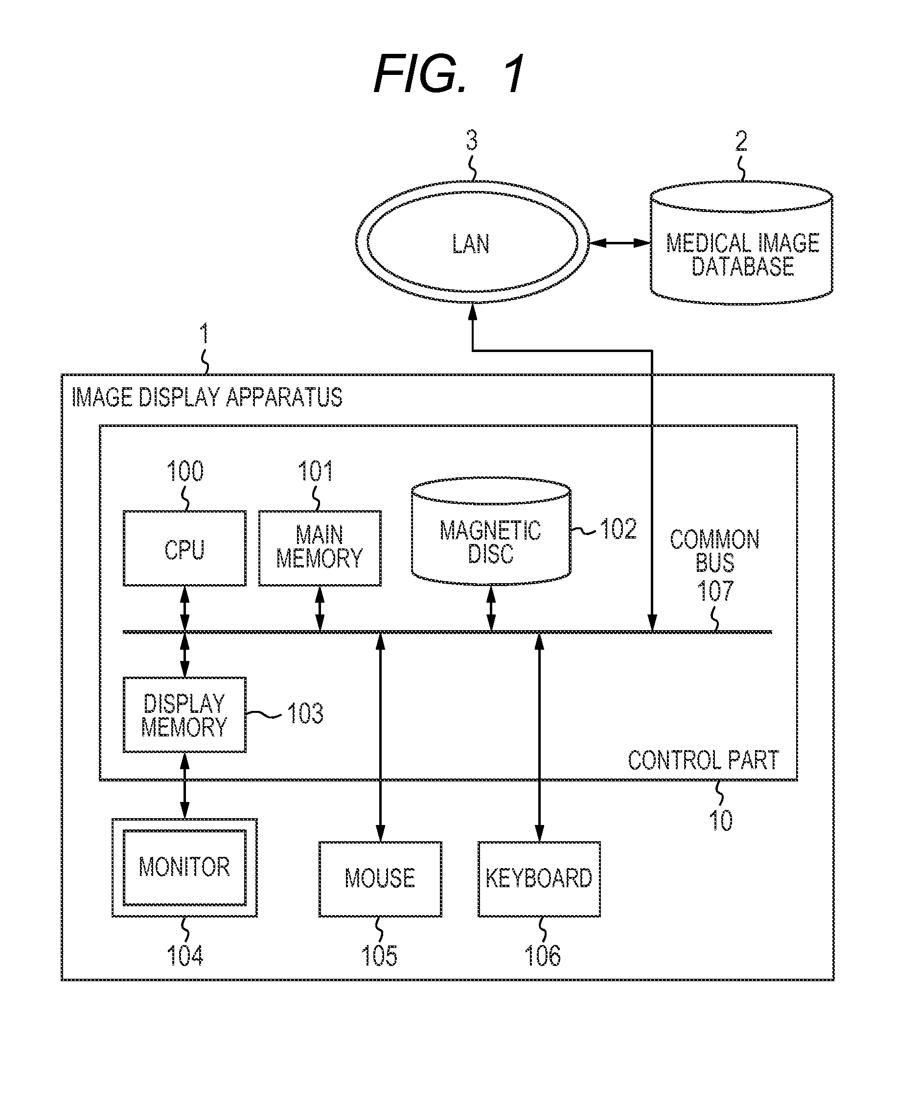
[0020]FIG. 1 is a diagram illustrating an exemplary configuration of an image display apparatus according to the first embodiment. The image display apparatus 1 has a control part 10, a monitor 104, a mouse 105, and a keyboard 106. The control part 10 has a central processing unit (CPU) 100, a main memory 101, a magnetic disc 102, and a display memory 103. When the CPU 100 executes a program stored in the main memory 101, various types of control such as control on the communication with a medical image database 2 and control over the image display apparatus 1 are performed.

[0021]The CPU 100 mainly controls operations of the components of the image display apparatus 1. The main memory 101 stores a control program executed by the CPU 100 and provides a workspace for the CPU 100 to execute the program. The magnetic disc 102 stores an operating system (OS), a device drive for peripheral devices, and application programs including programs for performing processes such as a diagnosis su...

second embodiment

[0052]The first example of the method of setting the display parameters is used in step S512 of the first embodiment will be discussed. Specifically, the display skip intervals for the sagittal cross sectional image, the coronal cross sectional image, and the axial cross sectional image are set in proportion to the distances Dx, Dy, Dz in each of the coordinate axes. In the second embodiment, the image display method is further determined for each of the coordinate axes at this moment. Here, examples of the image display method include the MIP (Maximum Intensity Projection) image display, the MinIP (Minimum Intensity Projection) image display, and the average image display. The MIP image, the MinIP image, and the average image are respectively created by calculating the maximum value, the minimum value and the average value for the pixel value at respective pixel position from a plurality of adjacent cross sectional images.

[0053]In the above example, determining the image display me...


PUM


Abstract

The invention provides an image display apparatus for displaying three cross sectional images for enabling efficient observation of a three-dimensional distribution of the images between a plurality of positions of interest when there are the plurality of positions of interest (abnormal shadow candidates) in three-dimensional medical image data. The apparatus determines a display switch parameter for each coordinate axis according to a positional relationship between a first position of interest and a second position of interest on a displayed image for each coordinate axis, and displays the cross sectional images by switching the cross sectional images in parallel from the first position of interest toward the second position of interest according to the determined display switch parameter.

Description

BACKGROUND OF THE INVENTION[0001]1. Field of the Invention[0002]The present invention relates to a technique of simultaneously displaying a plurality of cross sectional images of three-dimensional medical image data.[0003]2. Description of the Related Art[0004]Three-dimensional medical image data can be made into groups of cross sectional images respectively in the three orientations of cross sections called an axial cross section (cross section dividing the trunk at any height), a coronal cross section (cross section dividing the trunk into anterior and posterior halves), and a sagittal cross section (cross section dividing the trunk into right and left halves). Each group of cross sectional images consists of a plurality of cross sectional images put in each of the three orientations of cross sections. Conventional techniques are capable of simultaneously displaying the three cross sectional images by selecting an image from each group of cross sectional images and displaying the ...

Claims


Application Information

Patent Timeline
Patent Type & Authority Patents(United States)
IPC IPC(8): G06T15/00
CPCG06T2207/20101G06T19/00G06T7/0012G06T2200/04G06T2210/41G06T2207/20036G06T2207/30061G06T2219/028A61B6/03A61B5/055
Inventor IIZUKA, YOSHIOSATOH, KIYOHIDEMORINAGA, HIDEHIKOYOSHINO, AKIRASATO, MAIKO
Owner CANON KK
Why Eureka
Try Eureka