Lens barrel

a barrel and lens technology, applied in the field of lenses barrels, can solve the problems of thickness dimension and increase of the camera body (imaging apparatus) and achieve the effect of reducing the thickness dimension and simple configuration

Inactive Publication Date: 2014-05-20
RICOH KK
View PDF42 Cites 13 Cited by
  • Summary
  • Abstract
  • Description
  • Claims
  • Application Information

AI Technical Summary

Benefits of technology

[0007]The present invention has been made in view of the aforementioned circumstances. An object of an embodiment of the present invention is to provide a lens barrel which has a simple configuration achieving reduction in a thickness dimension of a retractable lens housing provided outside an inside diameter of a movable lens barrel.

Problems solved by technology

This causes a problem that the camera body (imaging apparatus) is increased in size when viewed from the front (object side).
For this reason, the above-described conventional lens barrel fails to effectively use the space between the rear end of the retractable lens retaining frame and the base member in the retractable lens housing, and there is still room for reducing the thickness dimension of the retractable lens housing.

Method used


Image

  • Lens barrel
  • Lens barrel
  • Lens barrel

Examples


first embodiment

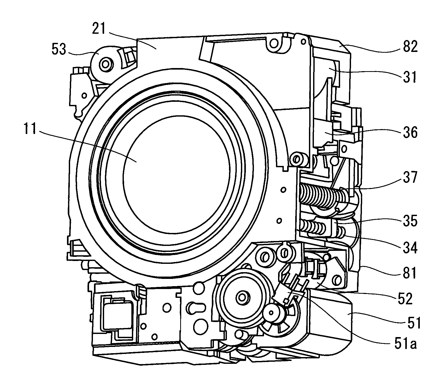
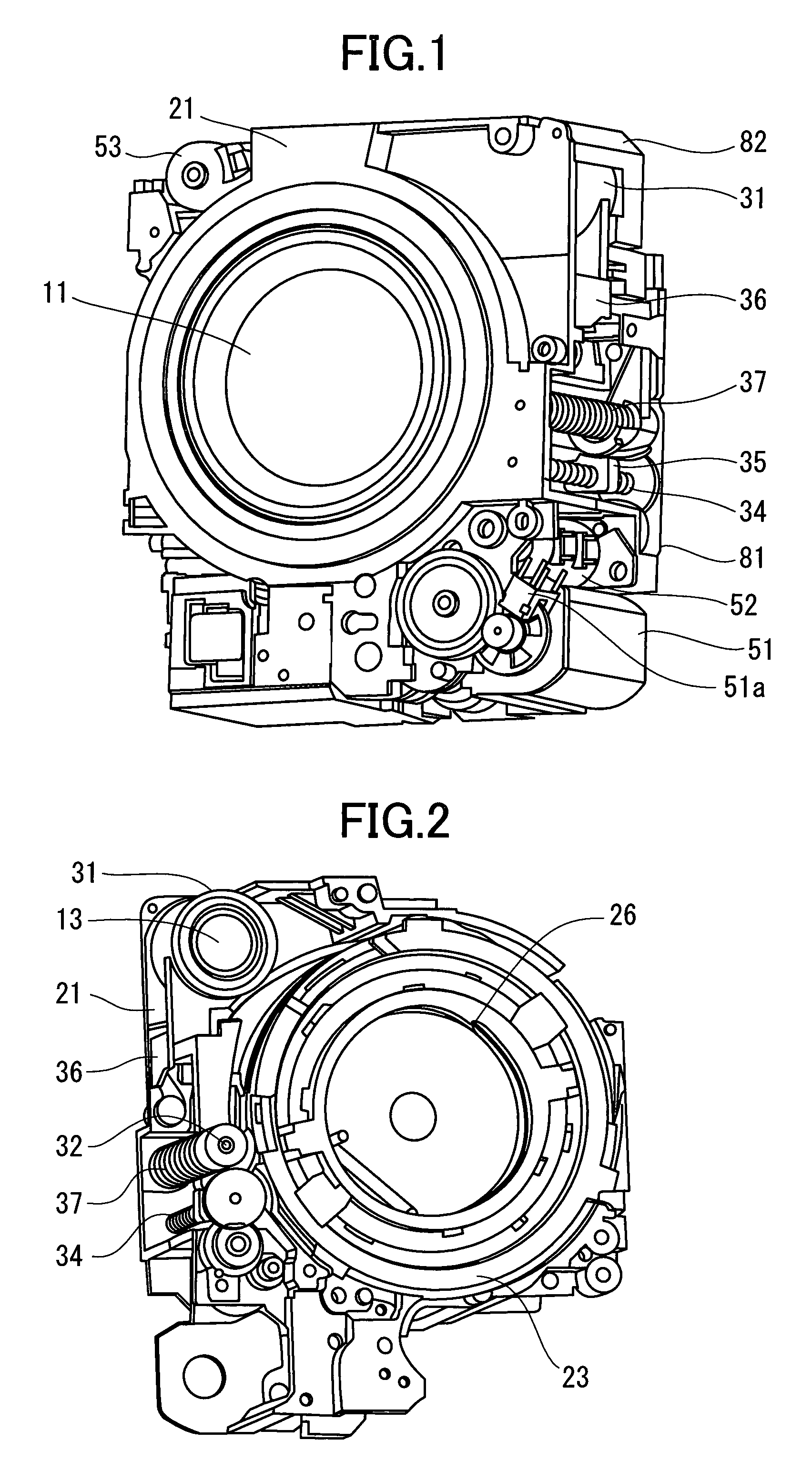
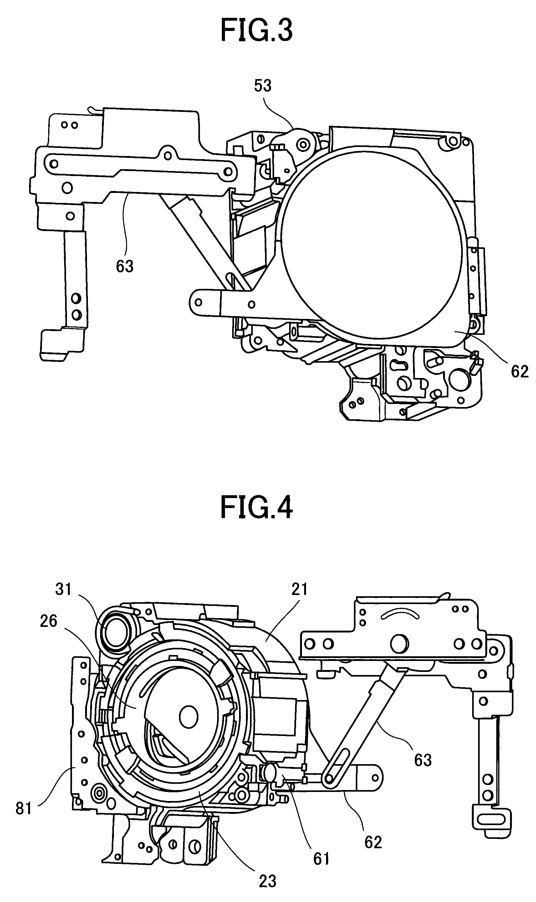
[0085]A lens barrel 10 of a first embodiment representing an example of a lens barrel according to an embodiment of the present invention will be described with reference to FIGS. 1 to 21. Note that FIGS. 1 to 16B and 20 show a configuration of a principal part of an optical system device including the lens barrel 10 according to an embodiment of the present invention and various operational states thereof.

[0086]In FIGS. 1 to 16B and 20, an optical system device provided with the lens barrel 10 includes a first lens group 11, a second lens group 12, a third lens group 13, a fourth lens group 14, a shutter-diaphragm unit 15, a solid-state image sensing device 16, a first lens retaining frame 17, a cover glass 18, a low-pass filter 19, a fixation frame 21, a first rotary cylinder 22, a first liner 23, a second rotary cylinder 24, a second liner 25, a cam cylinder 26, a straight moving cylinder 27, a third lens retaining frame 31, a third group main guide shaft 32, a third group sub-gu...

second embodiment

[0182]Next, a lens barrel 10A according to a second embodiment of the present invention will be described with reference to FIGS. 33 to 43. This second embodiment represents an example of a third lens retaining frame 31A serving as a retractable lens, which has a different manner of movements from that of the lens barrel 10 of the first embodiment. Basic structures of the lens barrel 10A of this second embodiment are similar to those of the lens barrel 10 of the above-described first embodiment. Accordingly, the same constituents are denoted by the same reference numerals and detailed description thereof will be omitted. First, a concept of the manner of movements of the third lens retaining frame 31A will be described with reference to FIG. 33.

[0183]As similar to the lens barrel 10 of the first embodiment, the lens barrel 10A of the second embodiment is also configured to locate a housing position of the third lens retaining frame 31A serving as the retractable lens retaining frame...

third embodiment

[0210]Next, a lens barrel 10B according to a third embodiment of the present invention will be described with reference to FIGS. 44 to 59. This third embodiment defines a third lens retaining frame 31B and a fourth lens retaining 41B as retractable lens retaining frames. Basic structures of the lens barrel 10B of this third embodiment are similar to those of the lens barrel 10 of the above-described first embodiment. Accordingly, the same constituents are denoted by the same reference numerals and detailed description thereof will be omitted.

[0211]First, outlines of configurations of the third lens retaining frame 31B and the fourth lens retaining frame 41B in the lens barrel 10B will be described. In this lens barrel 10B, as shown in FIGS. 44 and 45, the third lens retaining group 31B and the fourth lens group retaining frame 41B are used as the retractable lens retaining frames in order to use the third lens group 13 and the fourth lens group 14 as the retractable lens groups to b...


PUM


Abstract

A lens barrel includes a plurality of lens groups including a retractable lens group, a plurality of lens retaining frames to respectively retain the plurality of lens groups, a movable lens barrel to retain the plurality of lens retaining frames therein, and a lens retaining frame driving device to drive the lens retaining frames via the movable lens barrel. The lens retaining frames, the movable lens barrel and the lens retaining frame driving device move the plurality of lens groups between a collapsed state and a photographing state. The retractable lens retaining frame is movable between a position on a photographing axis and a position inside a housing located outside an inside diameter position of the movable lens barrel in the collapsed state by moving in a direction inclined relative to the photographing axis and moving in a direction orthogonal to the photographing axis.

Description

CROSS REFERENCE TO RELATED APPLICATIONS[0001]The present application is based on and claims priority from Japanese Application Numbers 2010-129984, filed on Jun. 7, 2010 and 2011-091180, filed on Apr. 15, 2011, the disclosure of which is hereby incorporated by reference herein in its entirety.TECHNICAL FIELD[0002]The present invention relates to a lens barrel configured to collapse a lens group in one mode and to use the lens group advanced to a predetermined position in another mode, or more specifically, to a lens barrel suitable for a zoom lens capable of changing a focal distance by moving multiple lens groups relative to each other on a photographing optical axis.BACKGROUND ART[0003]Imaging apparatuses such as digital still cameras and digital video cameras (hereinafter, collectively referred to as “digital camera”) are facing strong demands for improvements in imaging performance and portability. To meet these demand, some of imaging apparatuses are configured to, when shootin...

Claims


Application Information

Patent Timeline
Patent Type & Authority Patents(United States)
IPC IPC(8): G02B7/02
CPCG03B17/04G03B5/00G02B7/022G02B7/08
Inventor IWASAKI, TETSUYAKOYAMA, TERUNORI
Owner RICOH KK
Why Eureka
Try Eureka