Automated debugging system and method

a debugging system and automatic technology, applied in the field of debugging system and method, can solve problems such as code problems, mistakes and unexpected events, and debugging problems faced by developers worldwide, and achieve the effects of reducing the amount of output data produced, accurately determining, and effectively automating the tracing process

Inactive Publication Date: 2014-05-20
ITI SCOTLAND
View PDF9 Cites 9 Cited by
  • Summary
  • Abstract
  • Description
  • Claims
  • Application Information

AI Technical Summary

Benefits of technology

[0047]Embodiments of the present invention are directed to an automated system and method of debugging in which static analysis information is combined with execution tracing to reduce the amount of information that needs to be recorded dynamically (at run time). Because static analysis can determine detailed information about how a system can and can't behave, the amount of information recorded can be reduced. There are three aspects to this.
[0050]Finally, because the structure of the code is known by the static analysis engine, efficient compression techniques are possible, which are tailored to the particular code being traced. As a result, embodiments of the present invention combine traditional run-time debugging approaches with static analysis to vastly reduce the amount of output data produced and accurately determine the cause of failure rather than just the point of failure. The trace marker records can be optimally small. This technique effectively automates the tracing process in a way that is understandable to a static analysis engine. The result being that the whole process can be carried out automatically and vastly reduces the time taken to find the root cause of a run-time problem.
[0051]A further advantage is that because the tracing data produced is minimised, much larger execution runs can be recorded than in prior systems. Execution speed of instrumented code (and therefore production of a debugging report) is observed to be much better than with existing techniques due to both reduced number of trace statements and reduced amount of data recorded per statement. Another advantage is that historical traces can be kept for longer due to the limited overhead needed to retain the compact trace files.

Problems solved by technology

In the real world, mistakes and unexpected events happen.
Debugging is a problem faced by developers worldwide.
They have a problem in their code.
They have pinpointed the outward manifestation of the problem, using a dynamic analysis tool, but they have no clue as to the root cause.
The debugging to find the root cause of the problem (necessary to effect a fix) is often long and protracted.
On large poorly maintained code bases the debug time can run into weeks.
However, once a project reaches a stage where code is compiled and run, the help available diminishes significantly.
An error (either an exception or a spurious result) that arises at this stage is referred to as a run-time error.
However in the worst case the program may fail or even cause the whole operating system to become unstable or reboot.
Typically a spurious error is an errors in logic, arithmetic or the like that causes an unexpected result (such as 1+1 equalling 5).
It is not unusual for a run-time error to be missed by the test cases used in dynamic testing.
Unless the developer has had the foresight to place error handling routines in code, a run-time error is often simply presented to a user as an obscure operating system level error with a memory reference that takes considerable expertise and time to identify its cause.
Given the size of a code base for a typical project or system, tracing is generally not feasible for a whole system and must be applied in a piecemeal fashion.
Even then, the magnitude of logged data from tracing even selected modules can be significant and impair effective analysis of the problem.
Full path tracing produces large amounts of output data, limiting the size of execution to which it can be applied.
This is disadvantageous as the summary information gives only a vague idea of the area of a problem and also omits information on the full path traversed.

Method used


Image

  • Automated debugging system and method
  • Automated debugging system and method
  • Automated debugging system and method

Examples


Embodiment Construction

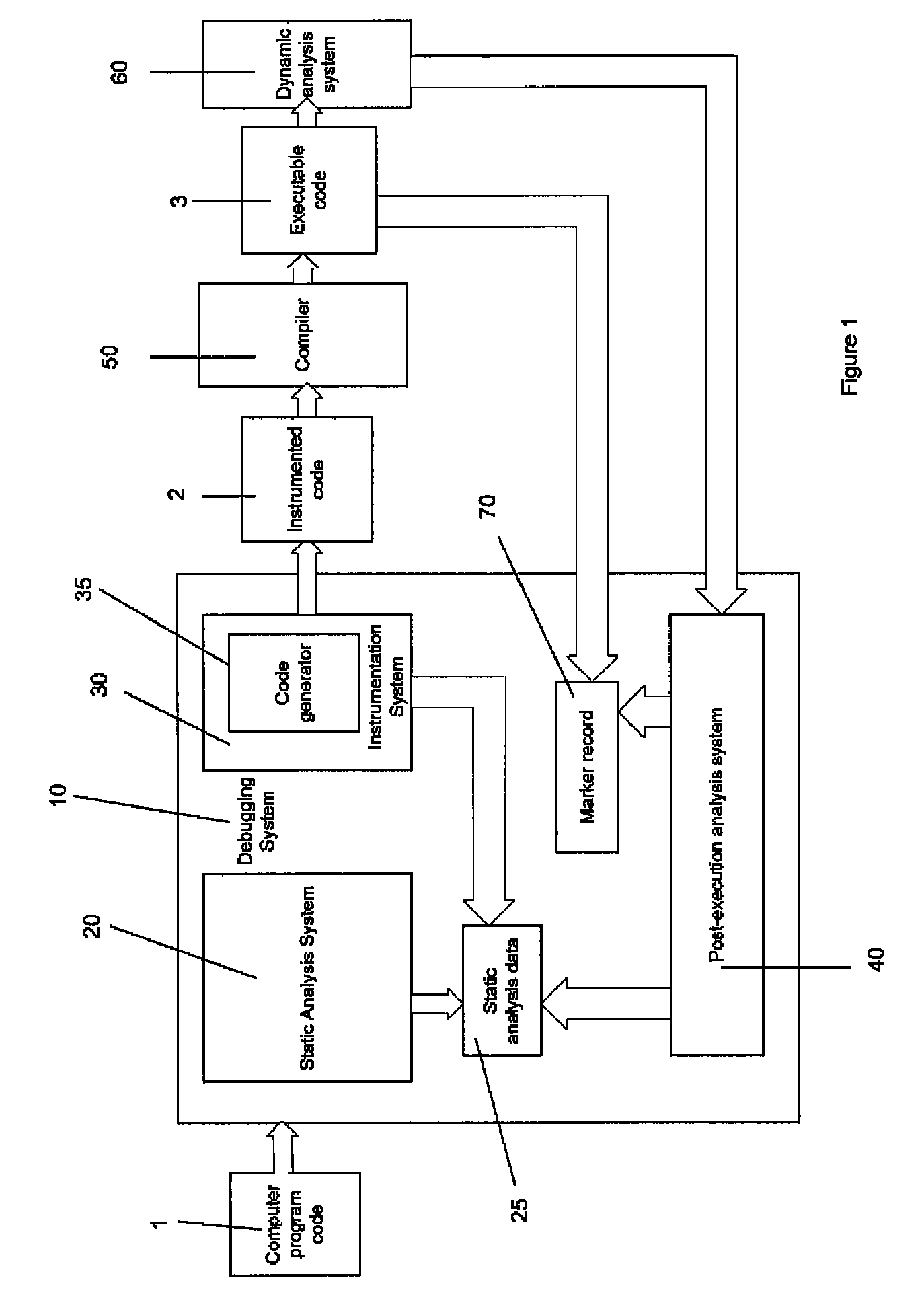
[0063]FIG. 1 is a schematic diagram of a debugging system according to an embodiment of the present invention.

[0064]The debugging system 10 includes a static analysis system 20, an instrumentation system 30 and a post-execution analysis system 40.

[0065]In use, the debugging system performs static analysis on computer program code 1 prior to compilation to generate static analysis data 25. Dependent on the static analysis data 25, the code is instrumented by the instrumentation system 30. The instrumented code 2 includes triggers for markers to be generated when a predetermined point in the code is reached during execution. The markers are uniquely labelled and the associated triggers are inserted by the instrumentation system 30 at points in the code determined from the static analysis data 25.

[0066]At execution time, the instrumented code 2 behaves in exactly the same way as the un-instrumented code 1, except for the fact that it records which parts of the software are executing an...


PUM


Abstract

System and method for automatically identifying a source of a run-time error in a computer system comprises a static analysis system (SAS), an instrumentation system (IS) and a post-execution analysis system (PEAS). The is arranged to generate static analysis data on computer program code (CPC) for the computer system, including information on possible behaviors of the CPC when executed. The IS is arranged to instrument the CPC by inserting marker triggers into the CPC that, generate a marker associated with each of a number of predetermined points in the CPC that would be reached during execution of the CPC. Each marker is, uniquely identifiable. The predetermined points are determined in dependence on the static analysis data. The PEASpost execution analysis system is arranged to processes data on a run-time error produced by execution of the instrumented CPC, wherein the generated markers and the static analysis data to identify the source of the run-time error.

Description

CROSS REFERENCE TO RELATED APPLICATIONS[0001]This application is a continuation under 35 U.S.C. §120 of International PCT Patent Application No. PCT / GB20101 / 001517, filed on Aug. 10, 2010, which claims the benefit of European Application Serial No. 09251528.7, filed Jun. 10, 2009, which are hereby incorporated by reference in their entirety herein.FIELD OF THE INVENTION[0002]The present invention related to a debugging system and method that is particularly applicable for use in debugging run-time errors in computer program code.BACKGROUND TO THE INVENTION[0003]In the ideal world, a system will be created correctly on its first iteration without mistakes and cater for all eventualities. In the real world, mistakes and unexpected events happen.[0004]This is certainly the case in computer software. It is not unusual in complex systems for components and routines to be written or created by different individuals or organisations. Indeed, it is not at all unusual to inherit what is term...

Claims


Application Information

Patent Timeline
Patent Type & Authority Patents(United States)
IPC IPC(8): G06F9/44
CPCG06F11/3612G06F11/3624
Inventor FINKING, ROBERTROBERTS, SIMONHEWSON, GRAHAM
Owner ITI SCOTLAND
Why Eureka
Try Eureka