Durable wall construction

Inactive Publication Date: 2014-05-27
HIGHLAND TECH
View PDF67 Cites 6 Cited by
  • Summary
  • Abstract
  • Description
  • Claims
  • Application Information

AI Technical Summary

Benefits of technology

The present invention is a building technology that allows for the rapid construction of durable structures using a combination of concrete and steel. This process can be used for the construction of multi-family dwellings that are affordable and require minimal maintenance. Additionally, reinforcement layers made up of welded-wire fabric and additional sheets of steel mesh are added to strengthen the concrete and support the structural assembly of each wall, as well as stabilize and support the rib lath during the application of concrete. Overall, this technology allows for the efficient and effective construction of high-quality buildings.

Problems solved by technology

Most of these traditional construction methods are both costly and time-consuming.
These systems require a central manufacturing facility, and experience high acquisition and transportation costs for all the necessary materials.
These modular construction methods also sacrifice the ultimate durability and longevity of the resulting structure, where too much emphasis has been placed on cost-reduction in order to meet limited construction budgets.
There have been several wall systems over the years that use shotcrete or pressurized concrete, none of which has been highly successful.
The Styrofoam panel system is inherently weaker, and therefore, makes it less durable and less suitable where high wind or seismic conditions exist.
The problem with these systems is that it is more difficult to apply the shotcrete to the walls because there is no rigid panel or diaphragm on which to place the shotcrete during the application process.
The more the panels or diaphragms move during application, the more difficult it is to get the shotcrete to adhere to the panel surface, where the flexing of the panels increases the rebound effect of the shotcrete, resulting in unacceptable amounts of wasted concrete.
The necessary building system and process to achieve these goals cannot require excessive amounts of costly skilled labor and cannot create excessive amounts of wasted materials.

Method used


Image

  • Durable wall construction
  • Durable wall construction
  • Durable wall construction

Examples


Embodiment Construction

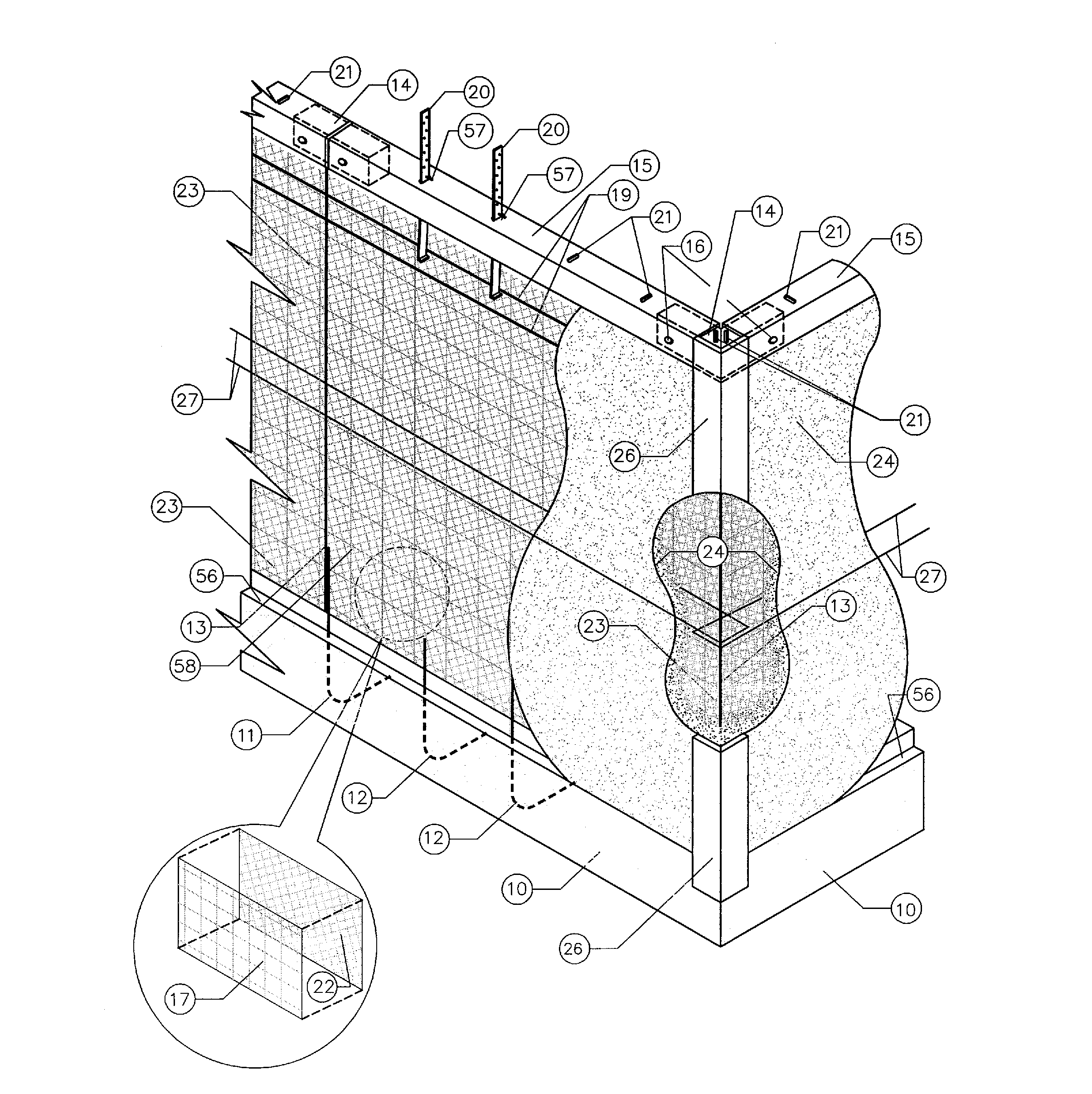
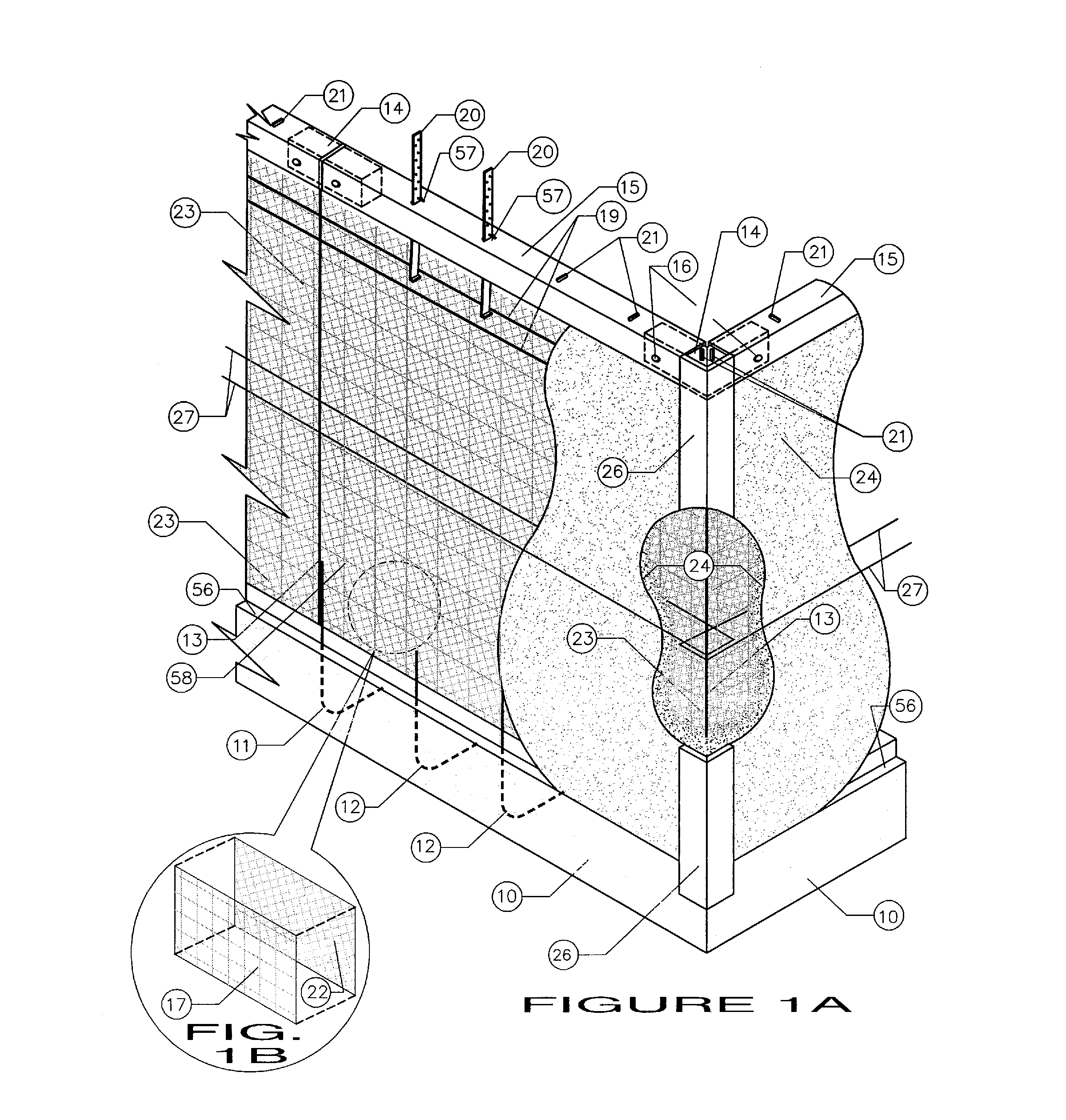
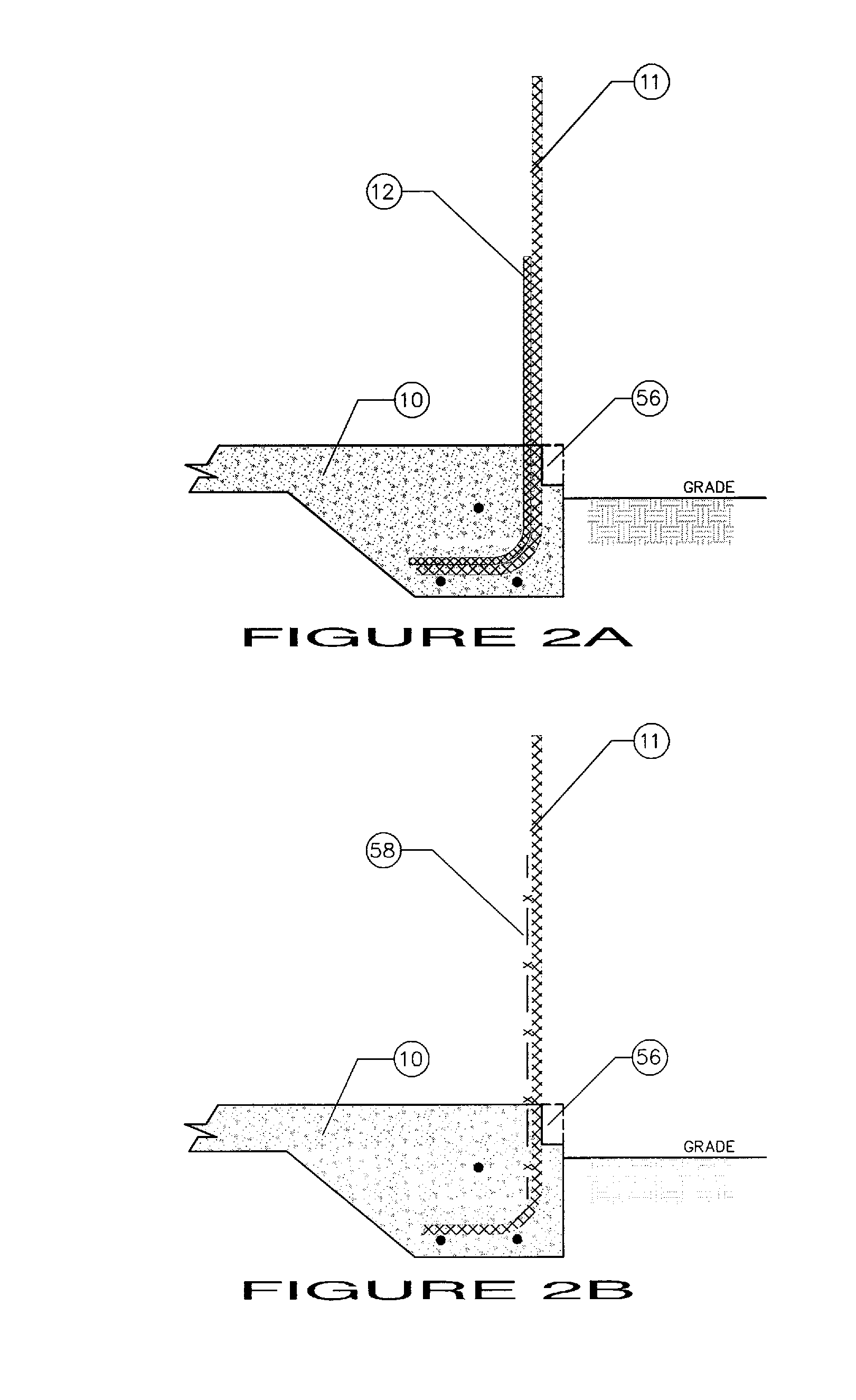
[0041]The following detailed description depicts a construction process and methodology that provides significant improvements over existing shotcrete panel systems in speed of assembly, simplification, construction stability, and reduction of materials waste. For simplicity, the construction methodology will be demonstrated by describing the assembly of one wall section between two vertical supports. This wall section could represent the wall between two corners of a structure or a representative section of a longer, straight wall.

[0042]The present invention involves a building system, implemented via a unique construction method and process, that provides for the construction of a fully integrated foundation and series of exterior and interior walls comprised of steel mesh and pressurized concrete, utilizing specialized, purpose-built, re-useable assembly components. Units can be built from virtually any structural layout or design. This process is particularly desirable for proje...


PUM


Abstract

A durable wall construction that is seamlessly integrated with a foundation and construction pad. The construction process incorporates stabilizing elements that rests a primary layer or sheet of welded-wire fabric on a foundation having rebar dowels protruding therefrom. Interlocking temporary upper guiderails are held in place by vertical rebar support rods. The temporary guiderails stabilize the top edge of the primary layer of welded-wire fabric, and rib lath is attached to the surface of the primary layer of welded-wire fabric to form a structural panel. Pressurized concrete is evenly applied to all of the inside and outside surfaces of the structural panels. Once the concrete has cured sufficiently, the upper stabilizing guide rails are removed to provide a durable wall.

Description

FIELD OF THE INVENTION[0001]The present invention is directed to the construction industry and, more particularly to a durable wall system and construction method.BACKGROUND OF THE INVENTION[0002]Most traditional residential construction is still carried out utilizing conventional methods and materials such as wood or metal frame structural components, masonry block, precast concrete panels, and cast-in-place concrete forms. These types of construction are universally recognized, but they require a high degree of sophistication and training in order for them to be useful. Most of these traditional construction methods are both costly and time-consuming.[0003]Large numbers of “prefab” or “modular” building systems have been brought to the market in recent years. These systems require a central manufacturing facility, and experience high acquisition and transportation costs for all the necessary materials. These modular construction methods also sacrifice the ultimate durability and l...

Claims


Application Information

Patent Timeline
IPC IPC(8): E04F13/04E04B1/24E04B9/00E04B1/18E04B1/16E04B1/19
CPCE04B2/845E04B1/161
Inventor HANSON, WILLIAM, C.
Owner HIGHLAND TECH
Why Eureka
Try Eureka