Light source device and projection display apparatus
a technology of projection display and light source device, which is applied in the direction of lighting and heating apparatus, instruments, optics, etc., can solve the problems of low reliability and difficulty in obtaining a high brightness, and achieve the effect of high efficiency
- Summary
- Abstract
- Description
- Claims
- Application Information
AI Technical Summary
Benefits of technology
Problems solved by technology
Method used
Image
Examples
embodiment 1
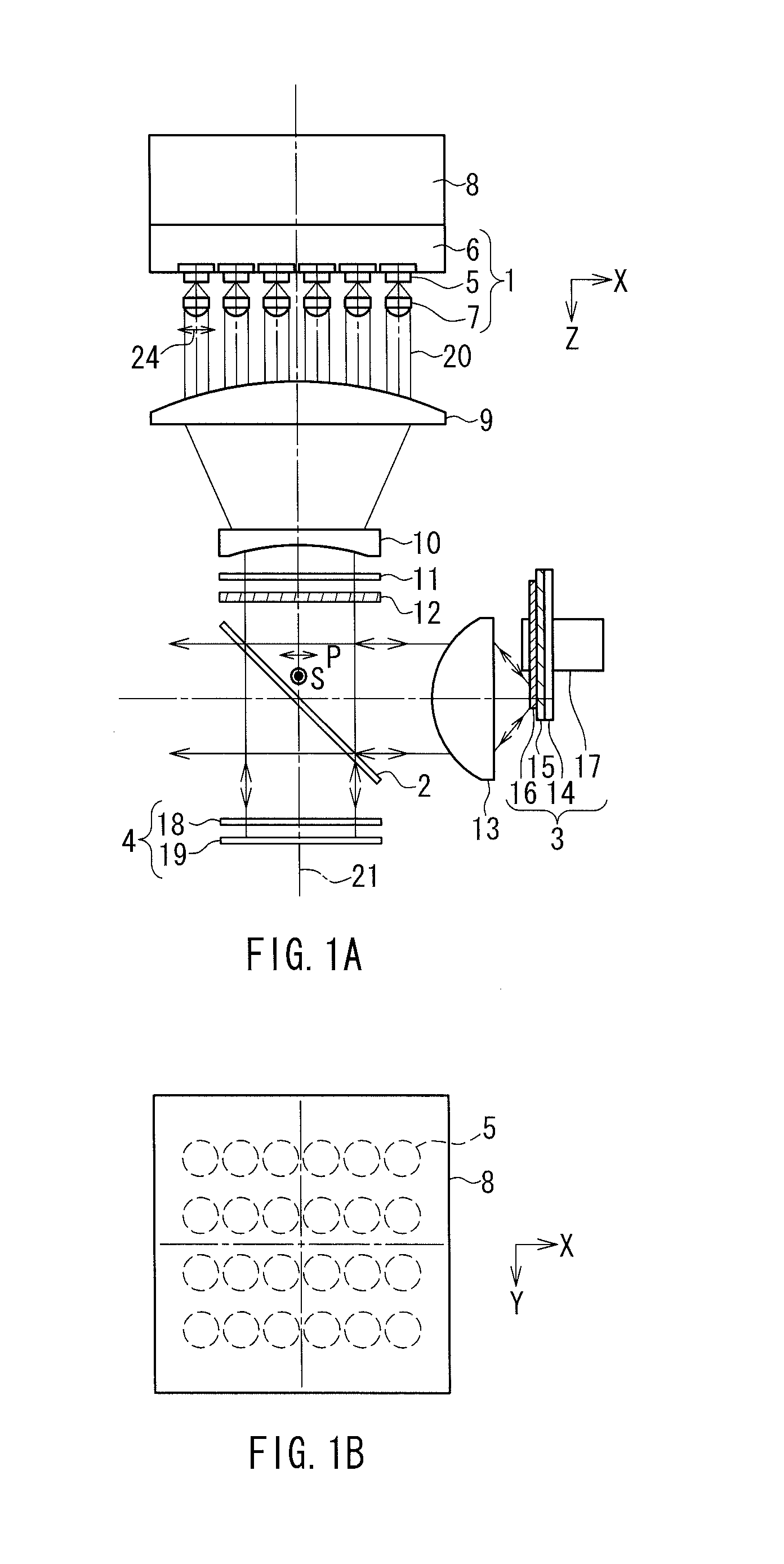
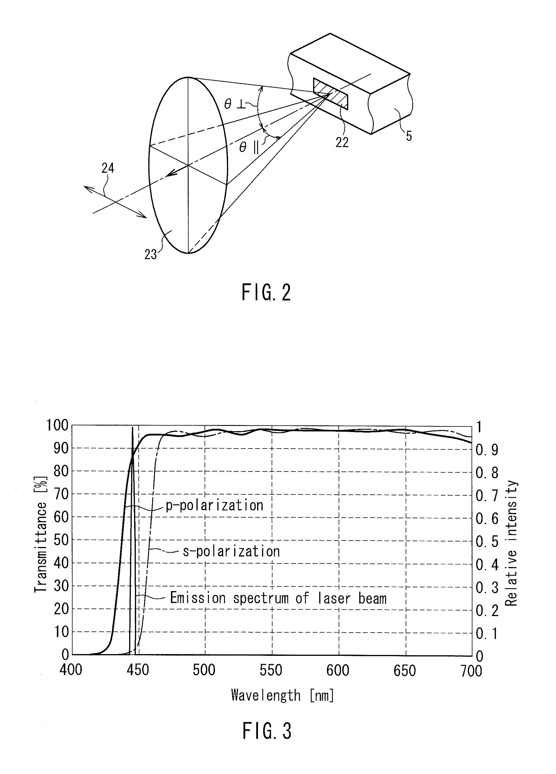
[0037]FIG. 1A is a front view showing a configuration of a light source device according to Embodiment 1 of the present invention. This light source device includes as basic elements a solid-state light source unit 1, a dichroic mirror 2, a fluorescence emission plate 3 and a polarization direction converting portion 4. The dichroic mirror 2 polarization separates the incident light by reflecting the s-polarization component and transmitting the p-polarization component. The fluorescence emission plate 3 is excited with the s-polarization component and emits fluorescence. The p-polarization component is converted into the s-polarization component by the polarization direction converting portion 4 and reflected by the dichroic mirror 2. Thereby, a color light from the fluorescence emission plate 3 and a color light from the polarization direction converting portion 4 are combined at the dichroic mirror 2 and exit there.
[0038]The solid-state light source unit 1 has semiconductor laser...
embodiment 2
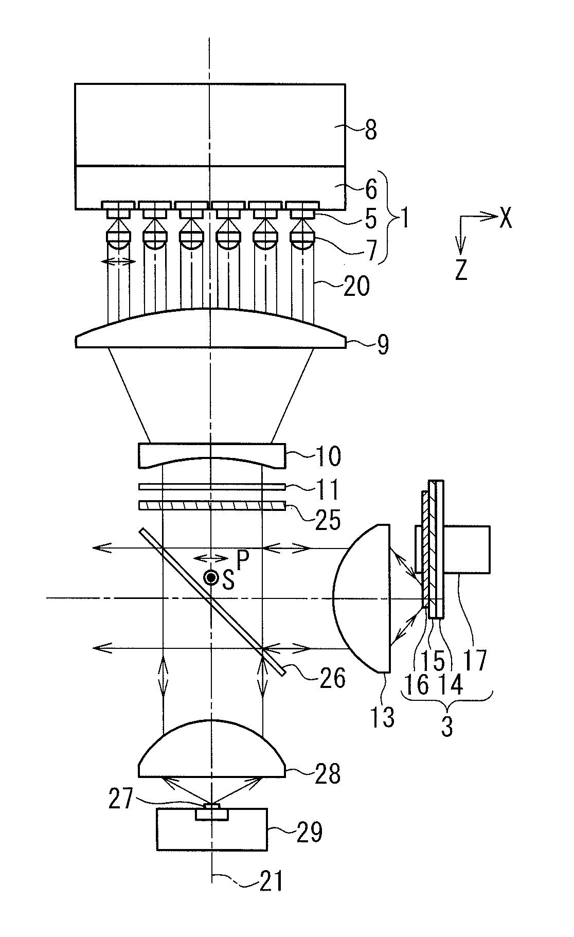
[0053]FIG. 5 is a front view showing a configuration of a light source device in Embodiment 2 of the present invention. This light source device is different from the light source device in Embodiment 1 in that the blue color light to be combined for obtaining a white color light is not a light exiting from the semiconductor laser 5 but a blue color light from a light-emitting diode. Except for some elements modified for this reason, the constructions of the elements such as the solid-state light source unit 1 and the fluorescence emission plate 3 are the same as those in Embodiment 1, and thus common elements are assigned with the same reference numbers in order to avoid duplicated explanation.
[0054]In FIG. 5, the half wave plate 25 and the dichroic mirror 26 correspond to the half wave plate 12 and the dichroic mirror 2 in FIG. 1A. However, the half wave plate 25 is configured to rotate the polarization direction of the linearly polarized light by about 90 degrees. Further, a blue...
embodiment 3
[0060]FIG. 7 shows a projection display apparatus in Embodiment 3 of the present invention. This projection display apparatus is constructed by using the light source device according to Embodiment 1. Therefore, common elements are assigned with the same reference numbers as in Embodiment 1 in order to avoid duplicated explanation.
[0061]In the present embodiment, a TN mode or a VA mode transmission type liquid crystal panel of an active matrix system, having a thin film transistor formed on the pixel region, is used for the light valve.
[0062]An illuminating portion that condenses the light exiting from the dichroic mirror 2 of the light source device so as to form an illumination light is constituted of a first and second lens array plates 30, 31, a polarization converting optical element 32, and a superimposing lens 33. A color-separating portion for color-separating the illumination light that has passed through the superimposing lens 53 and making the lights enter the liquid crys...
PUM
 Abstract
Description
Claims
Application Information
 - R&D
- Intellectual Property
- Life Sciences
- Materials
- Tech Scout
- Unparalleled Data Quality
- Higher Quality Content
- 60% Fewer Hallucinations
Browse by: Latest US Patents, China's latest patents, Technical Efficacy Thesaurus, Application Domain, Technology Topic, Popular Technical Reports.
© 2025 PatSnap. All rights reserved.Legal|Privacy policy|Modern Slavery Act Transparency Statement|Sitemap|About US| Contact US: help@patsnap.com


