Electronic endoscope

a technology of endoscope and endoscope, which is applied in the field of electronic endoscope, can solve the problems of not being generated by brightness control, increasing manufacturing cost, and complicated devices

Active Publication Date: 2014-05-27
HOYA CORP
View PDF25 Cites 2 Cited by
  • Summary
  • Abstract
  • Description
  • Claims
  • Application Information

AI Technical Summary

Benefits of technology

[0007]Therefore, an objective of the present invention is to provide an electronic endoscope that can generate and display a normal image and a high-quality fluorescent image of the same subject as the normal image, as real time images by brightness control of a single imaging optical system.
[0008]An electronic endoscope according to the present invention includes a white light source, an excitation light source, an imaging device, and a light amount controller. The white light source emits white light for illuminating a subject. The excitation light source emits excitation light for generating fluorescent light on the subject. The imaging device generates first image signals by receiving reflected light of the white light, the reflected light being reflected on the subject, and generates second image signals by receiving the fluorescent light. The light amount controller controls the amount of the white light. The light amount controller controlling the amount of the white light to lower the difference between a reflected light luminance (luminance of the reflected light received by the imaging device) and a fluorescent light luminance (luminance of the fluorescent light received by the imaging device), so that a normal image and a fluorescent image that are both real-time images representing the same subject at the time of receiving the reflected light and the fluorescent light can be generated. The normal image corresponds to the first image signals, and the fluorescent image corresponds to the second image signals.
[0010]The aperture control data, to lower the amount of the white light and to render the reflected light luminance and the fluorescent light luminance almost identical to each other, may be stored in the data memory, and the light amount controller may lower the amount of the white light based on the aperture control data, so that a pseudo-color image corresponding to the first image signals and the second image signals can be generated.

Problems solved by technology

Providing a plurality of imaging optical systems in an electronic endoscope complicates the device, increases the manufacturing cost.
On the other hand, in a current electronic endoscope having a single imaging optical system, a normal image and a fluorescent image as real time images of the same subject can not be generated by brightness control, and can not be displayed.

Method used


Image

  • Electronic endoscope
  • Electronic endoscope
  • Electronic endoscope

Examples


first embodiment

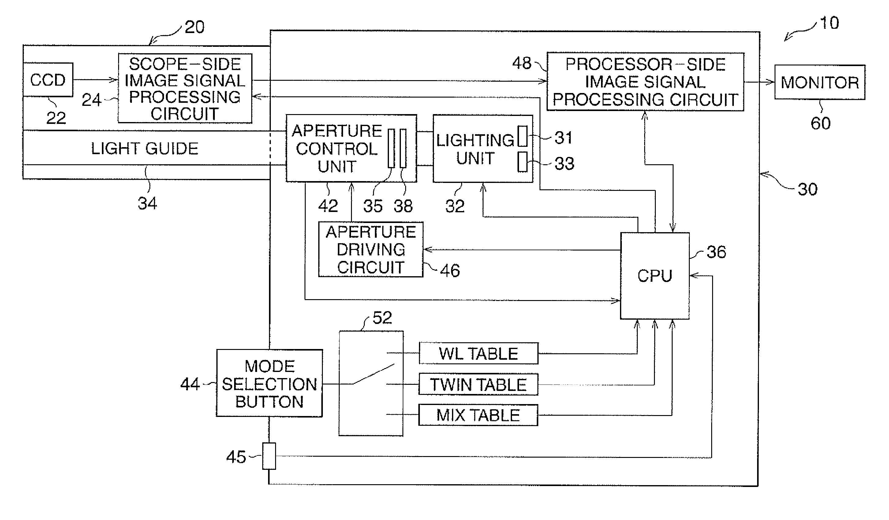
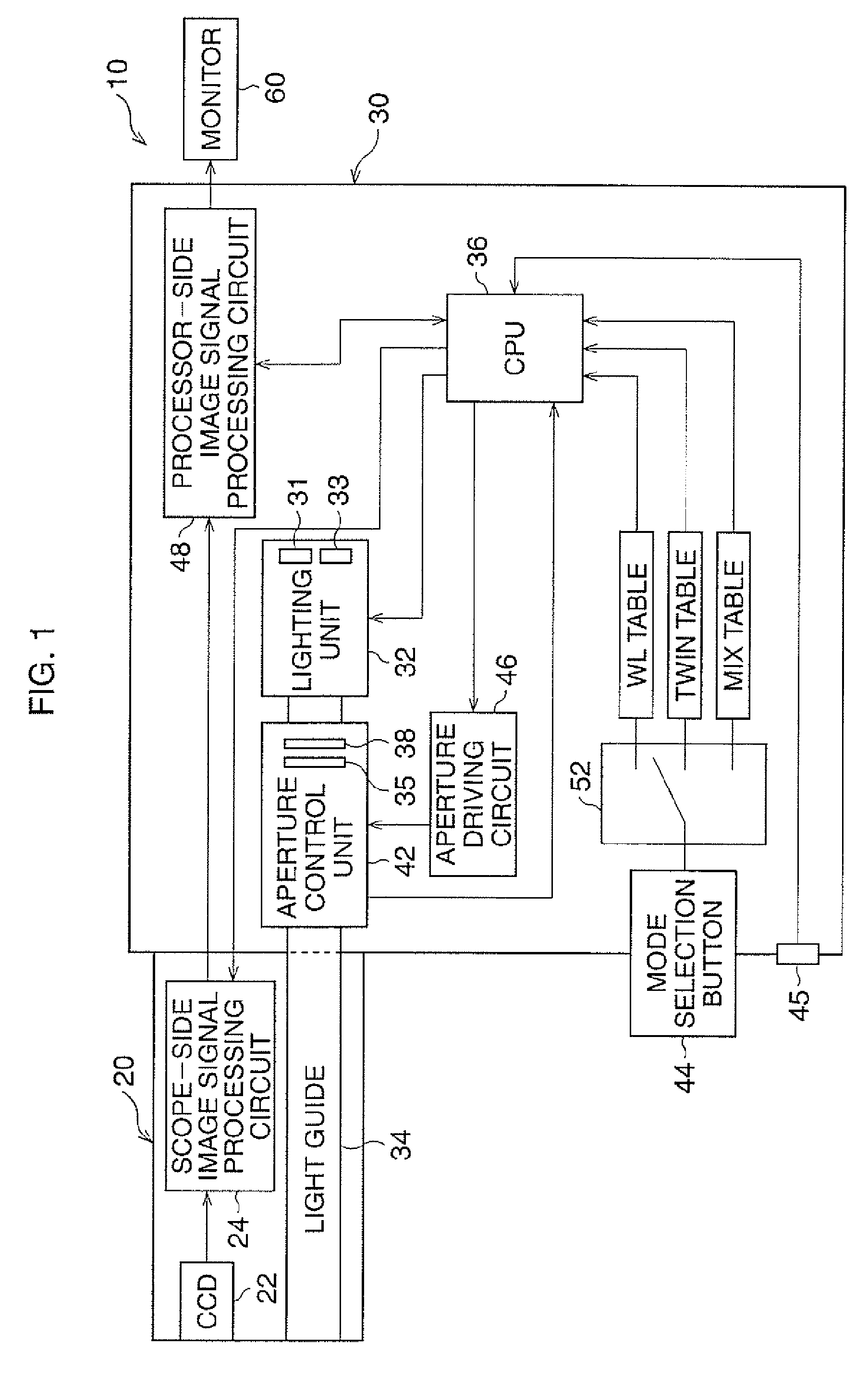
[0053]As explained above, in the electronic endoscope 10 of the first embodiment, a normal image and a fluorescent image representing the same subject as the normal image which have high qualities are generated. Further, the normal image and the fluorescent image can be generated and displayed as real time images, because storing image signals for generating the normal image and the fluorescent image in a memory, and carrying out different processes to the image signals for these images, are not required.

[0054]In the electronic endoscope 10 of the first embodiment, only a single imaging optical system, including the CCD 22 and other components, is provided, so that the structure of the electronic endoscope 10 can be simplified.

[0055]Note that the dimmer tables represented in FIG. 4 are only examples, and that dimmer tables actually used may not be limited to those represented in FIG. 4. For example, aperture drive voltages in accordance with the light amount levels may be set geomet...

second embodiment

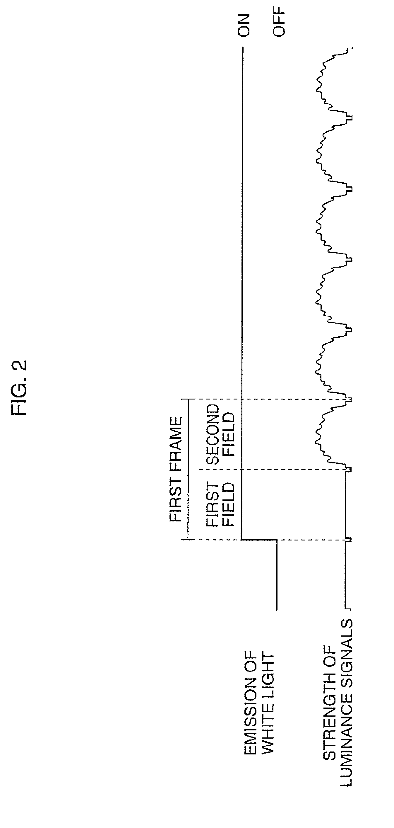
[0058]In the second embodiment, in the plurality images mode, where the white light and the excitation light are emitted alternately in the first field and the second field of one frame, only the luminance component of the normal image signals is transmitted to the CPU 36, as represented in FIG. 7. This control of the transmission of the image signals causes the CPU 36 to determine that the average strength of the luminance signals for a predetermined time of a plurality of frames has not been lowered.

[0059]That is, the luminance component of the fluorescent image signals is not written to the luminance component memory 54, and the luminance component of the normal image signals based on the reflected light of the white light, which is received by the CCD 22 one field before the fluorescent light is received, is written to the luminance component memory 54 thereof instead. As represented in FIG. 7, the luminance components of the original normal image signals are output to the CPU 3...


PUM


Abstract

An electronic endoscope includes a white light source, an excitation light source, an imaging device, and a light amount controller. The white light source emits white light for illuminating a subject. The excitation light source emits excitation light for generating fluorescent light on the subject. The imaging device generates first image signals by receiving reflected light of the white light, and generates second image signals by receiving the fluorescent light. The light amount controller controls the amount of the white light to lower the difference between a reflected light luminance and a fluorescent light luminance, so that a normal image corresponding to the first image signals and a fluorescent image corresponding to the second image signals that are both real-time images representing the same subject at the time of receiving the reflected light and the fluorescent light can be generated.

Description

BACKGROUND OF THE INVENTION[0001]1. Field of the Invention[0002]The present invention relates to an electronic endoscope, especially to an electronic endoscope that can display a fluorescent image.[0003]2. Description of the Related Art[0004]Currently, an electronic endoscope that enables a so-called fluorescence observation is known. In such an electronic endoscope, the property is utilized that when excitation light is emitted, a normal part of an observation subject generates fluorescent light; on the other hand, a diseased part, such as a cancer part, generates no fluorescent light. In certain such electronic endoscopes, a plurality of imaging optical systems are provided, so that a fluorescent image and a normal image based on reflected light of white light are generated and displayed on a monitor simultaneously.[0005]On the other hand, in a current electronic endoscope that enables a fluorescence observation and that has a single imaging optical system, obtained normal images ...

Claims


Application Information

Patent Timeline
Patent Type & Authority Patents(United States)
IPC IPC(8): A61B1/06
CPCA61B5/0071A61B1/0638A61B1/05A61B5/0084G02B23/2469A61B1/00009A61B1/043A61B1/0655
Inventor KOBAYASHI, SHOTARO
Owner HOYA CORP
Why Eureka
Try Eureka