Ceramic metal halide lamp

a ceramic metal and lamp technology, applied in the direction of gas discharge lamp details, electric discharge tubes, electrical apparatus, etc., can solve the problems of difficulty in improving both lamp efficiency and color rendering properties at the same time, and achieve the effect of lowering lamp efficiency

Inactive Publication Date: 2014-05-27
IWASAKI ELECTRIC CO LTD
View PDF0 Cites 1 Cited by
  • Summary
  • Abstract
  • Description
  • Claims
  • Application Information

AI Technical Summary

Benefits of technology

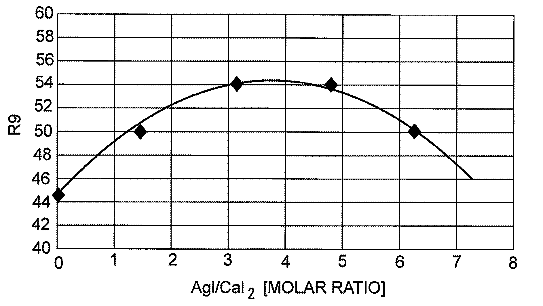
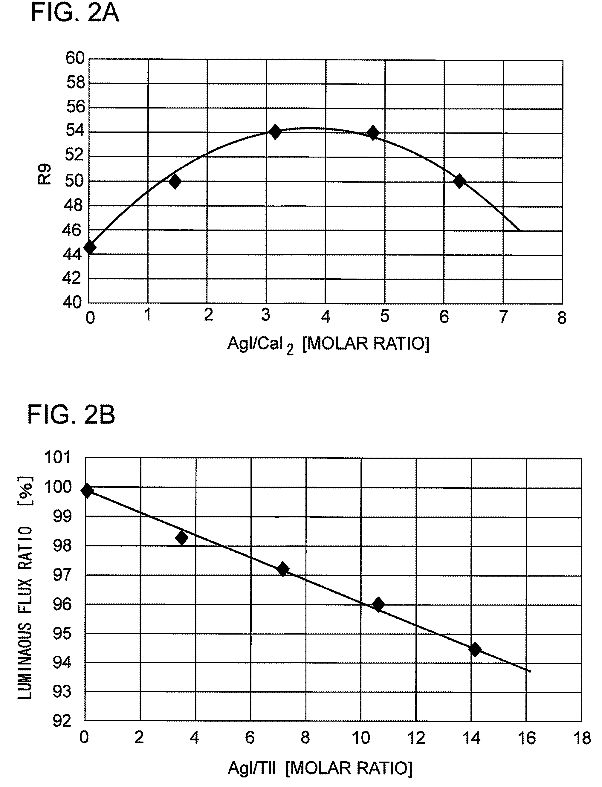
[0016]According to one or more embodiments of the present invention, it is possible to provide a ceramic metal halide lamp in which the color rendering property, especially the special color rendering index R9, can be improved while a lowering of lamp efficiency can be suppressed within a permissible range.

Problems solved by technology

However, in the ceramic metal halide lamp, lamp efficiency and color rendering properties are placed in a trade-off relationship and it has been said that it is difficult to improve both of the lamp efficiency and the color rendering properties at the same time.

Method used


Image

  • Ceramic metal halide lamp
  • Ceramic metal halide lamp
  • Ceramic metal halide lamp

Examples


Embodiment Construction

[0022]A ceramic metal halide lamp according to the embodiments of the present invention will hereinafter be described in detail with reference to the accompanying drawings. It should be noted that identical elements are denoted by identical reference numerals in the sheets of drawings and that they will not be described repeatedly.

[Ceramic Metal Halide Lamp]

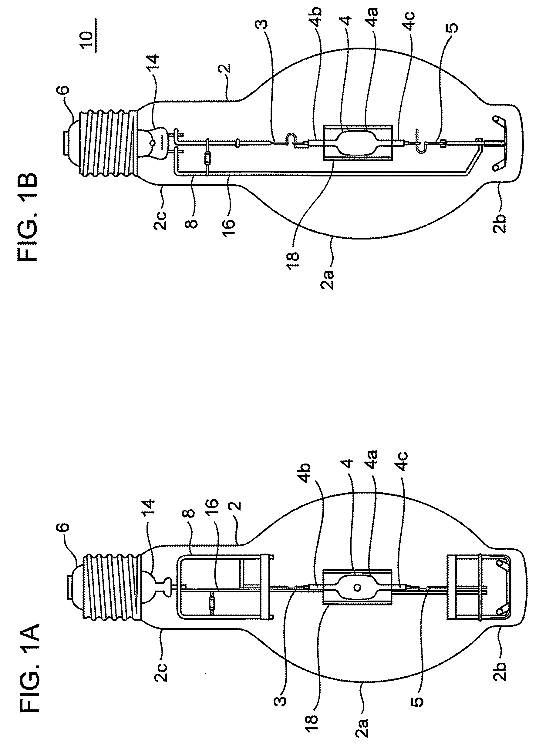
[0023]FIG. 1 is a diagram useful for explaining a structure of a ceramic metal halide lamp. FIG. 1A is a front view of a lamp and FIG. 1B is a side view thereof. A lamp 10 includes a luminous tube (arc tube) 4 which serves as a light-emitting portion sealed into the inside of an outer bulb 2. The circumference of the luminous tube is surrounded by a luminous tube protective sleeve (referred to also as an “inner tube”) 18. An E-type base 6 is bonded to the end portion of the outer bulb 2. The luminous tube 4 is supported to the lamp at its predetermined position by a mount 8 of a structure composed of assemblies of metal wires and...


PUM

PropertyMeasurementUnit
color temperatureaaaaaaaaaa
color rendering indexaaaaaaaaaa

Abstract

A ceramic metal halide lamp is provided in which color rendering properties, especially a special color rendering index R9, are improved without causing lamp efficiency to be lowered substantially. In one aspect, a ceramic metal halide lamp includes a luminous tube in the interior of an outer bulb. The luminous tube is made from translucent ceramics and includes a light-emitting portion into which metal halides, mercury and a starting gas are sealed and capillaries with a pair of electrode assemblies extended thereto disposed at both ends of the light-emitting portion. The light-emitting portion has sealed therein at least thulium iodide (TmI3), thallium iodide (TlI), sodium iodide (NaI) and calcium iodide (CaI2). The light-emitting portion has further sealed therein silver iodide (AgI). A quantity of the AgI falls within a range of 2≦(AgI / CaI2)[molar ratio]≦5 and within a range of 0<(AgI / TlI)[molar ratio]≦10.

Description

CROSS REFERENCE TO RELATED APPLICATIONS[0001]The present application claims the benefit of and priority to JP Application No. 2012-025594, filed Feb. 8, 2012, the entire disclosure of which is incorporated by reference herein.BACKGROUND OF THE INVENTION[0002]1. Field of the Invention[0003]The present invention relates to a ceramic metal halide lamp.[0004]2. Description of Related Art[0005]As a high-intensity discharge lamp (HID lamp), there exist, for example, a high-pressure mercury lamp, a high-pressure sodium lamp, a metal halide lamp and a ceramic metal halide lamp. The HID lamp is able to produce light by effectively utilizing discharges occurred between electrodes. Therefore, as compared with incandescent electric lamps, the HID lamp has various characteristics such as being large in luminous flux so as to become suitable for use in illumination of a large-scale area and being excellent in energy efficiency.[0006]As to the HID lamp, in 1960s, there have been developed metal ha...

Claims


Application Information

Patent Timeline
Patent Type & Authority Patents(United States)
IPC IPC(8): H01J17/20
CPCH01J61/125H01J61/827H01J61/18
Inventor SASAI, YASUSHI
Owner IWASAKI ELECTRIC CO LTD
Why Eureka
Try Eureka