Method and apparatus for diagnosing electrochemical sensor

a technology of electrochemical sensor and diagnostic method, which is applied in the direction of resistance/reactance/impedence, instruments, measurement devices, etc., can solve the problems of inability to ensure high reliability, inability to accurately detect gas to be detected, etc., to achieve accurate reflection of resistance component (impedance), and reduction of conductivity in the electrolyte

Active Publication Date: 2014-05-27
OSAKA GAS CO LTD
View PDF9 Cites 1 Cited by
  • Summary
  • Abstract
  • Description
  • Claims
  • Application Information

AI Technical Summary

Benefits of technology

[0017]Therefore, the means according to the present aspect can straightforwardly and reliably diagnose whether or not the sensor is in an error state in which there is not enough moisture or no moisture at all in the electrolyte (desiccated state or completely dry state) and the resistance in the electrolyte of the electrochemical sensor has increased.
[0045]According to this aspect, as when applying an alternating current to an electrochemical sensor as described earlier, applying an alternating voltage to an electrochemical sensor produces a state in which the reaction resistance component (impedance) at the sensing electrode and the opposite electrode in the equivalent circuit can be virtually ignored, and this is an indicator that more accurately reflects the resistance component (impedance) of the electrolyte, but the output current corresponding to this resistance component (impedance) is also an indicator that more accurately reflects the resistance component (impedance) of the electrolyte. A reduction in conductivity in the electrolyte when there is not enough or no moisture at all in the electrolyte (desiccated state or completely dry state) causes the output current of the electrolyte to decrease when an alternating voltage is applied. Therefore, an error state can be diagnosed more accurately and reliably when the output current of the electrolyte is decreasing relative to the normal current in the normal state. When using the output voltage instead of the output current, the electrochemical sensor can be diagnosed to be in an error state when an increase in voltage is found relative to the normal voltage, which is the output voltage of the electrochemical sensor in the normal state.

Problems solved by technology

Specifically, when the electrolyte solution or solid electrolyte becomes dry, the output of current by the electrochemical sensor decreases irrespective of the concentration of the gas to be detected, producing a problem in that the sensor cannot accurately detect the concentration of the gas to be detected.
Merely diagnosing that an error has started to occur when moisture has completely dried, however, risks creating a period during which the gas to be detected cannot be accurately detected and high reliability cannot be ensured in a case such as when the electrochemical sensor is used, for example, in an alarm device or the like that demands high reliability.

Method used


Image

  • Method and apparatus for diagnosing electrochemical sensor
  • Method and apparatus for diagnosing electrochemical sensor
  • Method and apparatus for diagnosing electrochemical sensor

Examples


first embodiment

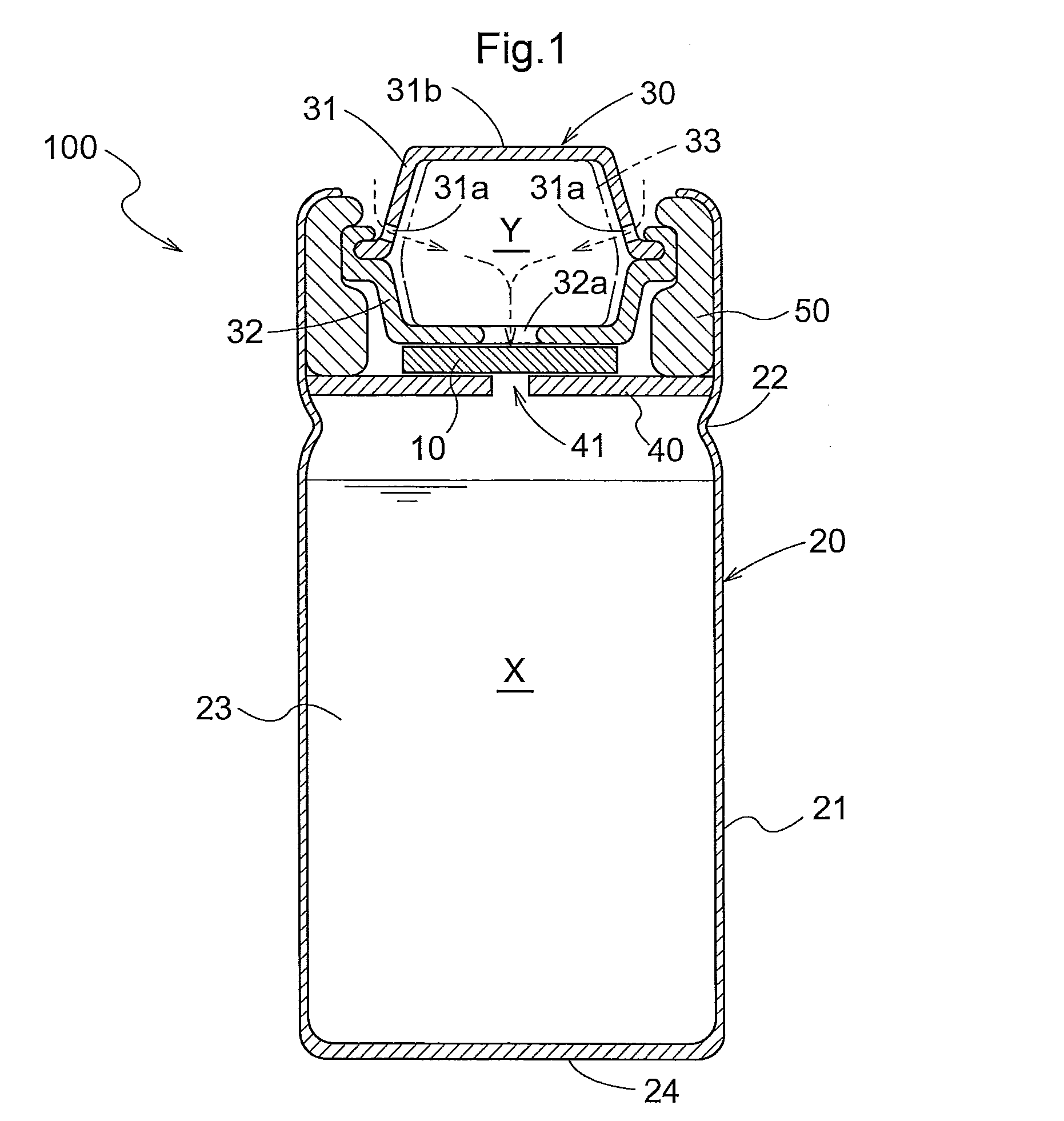
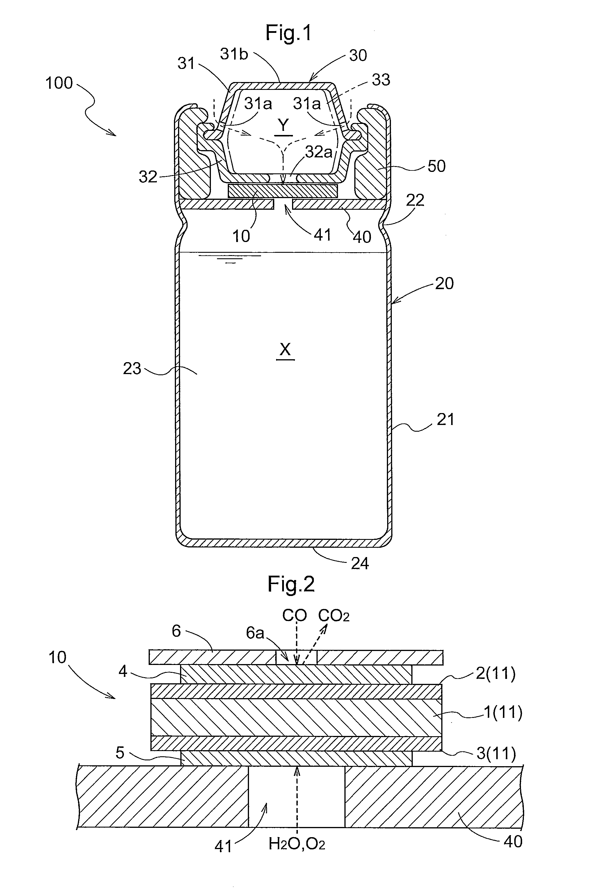
[0086]The sensor means 11 in the sensor unit 10 of the electrochemical sensor 100 is formed by connecting the anode 2 and the cathode 3 to the two sides (top and bottom) of the electrolyte layer 1 as shown in FIG. 2, but the sensor means 11 can be considered as corresponding to an equivalent circuit such as shown in FIG. 6. Specifically, the anode 2 is equivalent to a parallel connected configuration of a reaction resistor R2 and a capacitor (electric double layer capacitor) C2, the cathode 3 is equivalent to a parallel connected configuration of a reaction resistor R3 and a capacitor (electric double layer capacitor) C3, and the electrolyte layer 1 is equivalent to a resistor R1. Therefore, the sensor means 11 corresponds to an equivalent circuit in which the parallel connected configuration of the anode 2 is connected in series to the parallel connected configuration of the cathode 3 with the resistor R1, which is the electrolyte layer 1, in between.

[0087]By having an alternating ...

second embodiment

[0102]In the first embodiment described earlier, the diagnosing means 306 diagnoses whether or not a sensor is in an error state according to whether or not the impedance of the electrolyte layer 1 increases when an alternating current is applied. When a pulse rectangular voltage is applied instead of an alternating current, however, the output voltage of the electrochemical sensor corresponds to the impedance of the electrochemical sensor. Therefore, whether or not a sensor is in an error state can also be diagnosed by intermittently detecting the impedance of the electrochemical sensor when an alternating current is flowing by detecting the output voltage of the electrochemical sensor when a pulse rectangular voltage is applied.

[0103]A more detailed description now follows. As shown in FIG. 8, the diagnostic apparatus 300 comprises a load resistor 301 (for example, a 1 kΩ load resistor) and an electrochemical sensor 100 connected in series, power source means 302 for applying a co...


PUM


Abstract

A method and apparatus for diagnosing an electrochemical sensor that detects the concentration of a gas are operative for diagnosing whether or not the sensor is in an error state due to a rise in a resistance in the electrolyte of the sensor. Such detection is made on the basis of a current flowing between a sensing electrode and an opposite electrode or a voltage corresponding to the current. A method for diagnosing an electrochemical sensor having a solid or liquid electrolyte between a sensing electrode and an opposite electrode detects the concentration of the gas to be detected on the basis of a current flowing between the sensing electrode and the opposite electrode, or a voltage corresponding to the current. Whether or not the electrochemical sensor is in an error state is diagnosed on the basis of a resistance of the electrolyte between the two electrodes of the electrolyte.

Description

BACKGROUND OF THE INVENTION[0001]1. Field of the Invention[0002]The present invention relates to a diagnostic method for diagnosing an electrochemical sensor provided with a solid or liquid electrolyte between a sensing electrode for contacting a gas to be detected and an opposite electrode and designed for detecting the concentration of the gas to be detected on the basis of a current flowing between the sensing electrode and the opposite electrode or a voltage corresponding to this current, and to an electrochemical sensor diagnostic apparatus.[0003]2. Description of the Related Art[0004]An electrochemical sensor usually comprises a sensing electrode and an opposite electrode having an electrolyte solution or a solid electrolyte in between, and is configured to enable detection of the concentration of a gas to be detected in accordance with an output of a current generated by the sensing electrode oxidizing the gas to be detected or a voltage corresponding to this current (hereaft...

Claims


Application Information

Patent Timeline
Patent Type & Authority Patents(United States)
IPC IPC(8): G01R27/08G01R31/08
CPCG01N33/007
Inventor NONAKA, ATSUSHIOHNISHI, HISAONONAKA, HIDEMASANAKAYAMA, TOSHIROINOUE, TOMOHIROKATO, YUKI
Owner OSAKA GAS CO LTD
Why Eureka
Try Eureka