

Transmission delay based RFID tag
a technology of delay and delay, applied in the field of radio frequency identification (rfid) tags, can solve the problems of limited battery life and more limited read distance of passive tags, and achieve the effect of substantial uniform impedan
- Summary
- Abstract
- Description
- Claims
- Application Information
AI Technical Summary
Benefits of technology
Problems solved by technology
Method used
Image

Examples
Embodiment Construction
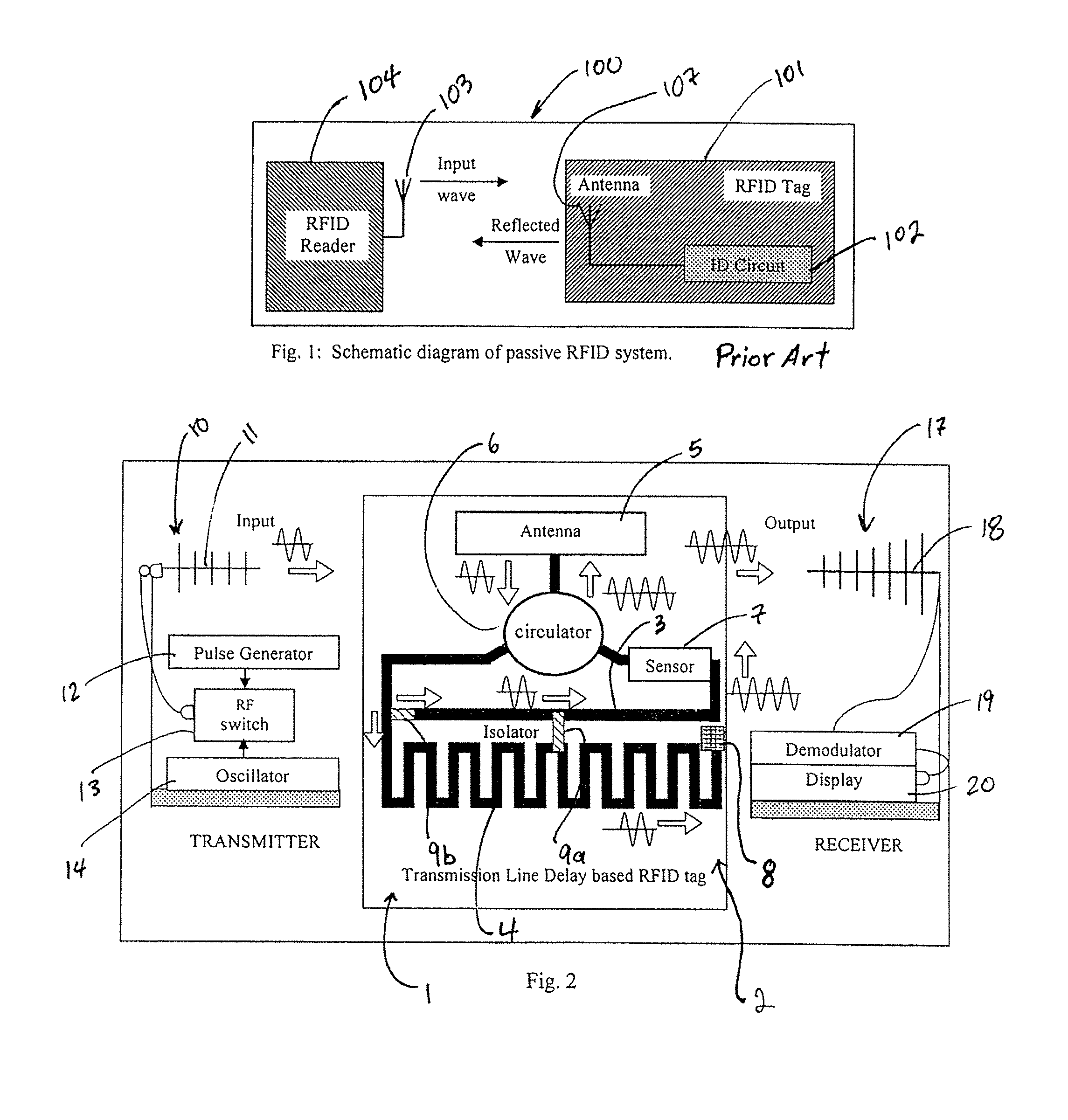
[0007]One embodiment of the present invention forms a chipless RFID tag system. The system includes a transmitter sending an input signal and a tag substrate having a first and a second microstrip. The second microstrip is at least twice as long as the first microstrip and has substantially uniform impedance along its length. The system further includes at least one tap positioned between the first and second microstrips allowing one-way transmission of the input signal from the second to the first microstrip.
[0008]Another embodiment of the present invention also forms a chipless RFID tag system. This system includes a transmitter sending an input signal and a tag substrate. The tag substrate has at least one microstrip and the microstrip has a first portion with a first impedance and a second portion with a second impedance different from the first impedance. The system further includes a receiver detecting at least two reflections from an interface of the first and second impedanc...
PUM
 Abstract
Description
Claims
Application Information