Fluid bearing assembly

a technology of fluid film and bearings, which is applied in the direction of bearings, shafts and bearings, etc., can solve the problems of only controlling the threshold of tension that needs to be applied to the web, the processing speed of the web, and the web handling system can only be improved, so as to achieve the effect of convenient use and low manufacturing cos

Inactive Publication Date: 2014-06-03
CARPE DIEM TECH
View PDF14 Cites 5 Cited by
  • Summary
  • Abstract
  • Description
  • Claims
  • Application Information

AI Technical Summary

Benefits of technology

[0021]It is another object of the present invention to provide a new and improved fluid film bearing that is particularly well-suited for use in low inertia, low friction rollers adapted to handle relatively high speed and fragile running webs.
[0023]It is still another object of the present invention to provide a fluid film bearing of the type described above that allows for acute adjustability of the size of the air gap between inner and outer components after assembly.
[0025]It is another object of the present invention to provide a fluid film bearing of the type described above that has a limited number of parts, is inexpensive to manufacture and is easy to use.

Problems solved by technology

However, one of the significant obstacles in improving web processing speeds is that web handling systems often rely upon commercially available rollers that experience direct solid-to-solid contact between moving parts.
However, this threshold of tension that needs to be applied to the web can only be controlled to the extent that the level of friction for each mechanical roller is known.
Because the level of friction experienced by traditional mechanical rollers is not precisely determinable, excess tension is often applied to the web during transport which, in turn, can result in considerable distortion and stress to the web.
With very sensitive webs, this distortion and stress can result in various types of irreversible damage, such as stress birefringence, crack propagation or, in certain circumstances, complete breakage of the web, which is highly undesirable.
Although well-known in the art, rollers of the type described in the '513 patent that rely upon the principal design features of a cylindrical air bearing have been found to suffer from a notable drawback.
Since these geometric properties are permanently defined, or fixed, upon completion of the manufacture of the individual components, adjustability of fluid bearing performance characteristics is typically unattainable once machined.
However, it is to be understood that because many of the determining dimensions are considerably small by design, the machining precision that is required cannot be reliably obtained (e.g., due to normal machining tolerances).
However, this significant increase in overall roller size renders it considerably expensive to manufacture and rather difficult to integrate into relatively compact web-handling systems.
As a first shortcoming, the counterbalancing effect of the opposing conical portions renders such bearings incapable of gap adjustment once assembled.
As a second shortcoming, conical bearings of the type as described above have been found to be considerably difficult and expensive to manufacture and assemble.
As a third shortcoming, conical bearings of the type as described above have been found to perform poorly due to the occurrence of resonance.

Method used


Image

  • Fluid bearing assembly
  • Fluid bearing assembly
  • Fluid bearing assembly

Examples


first embodiment

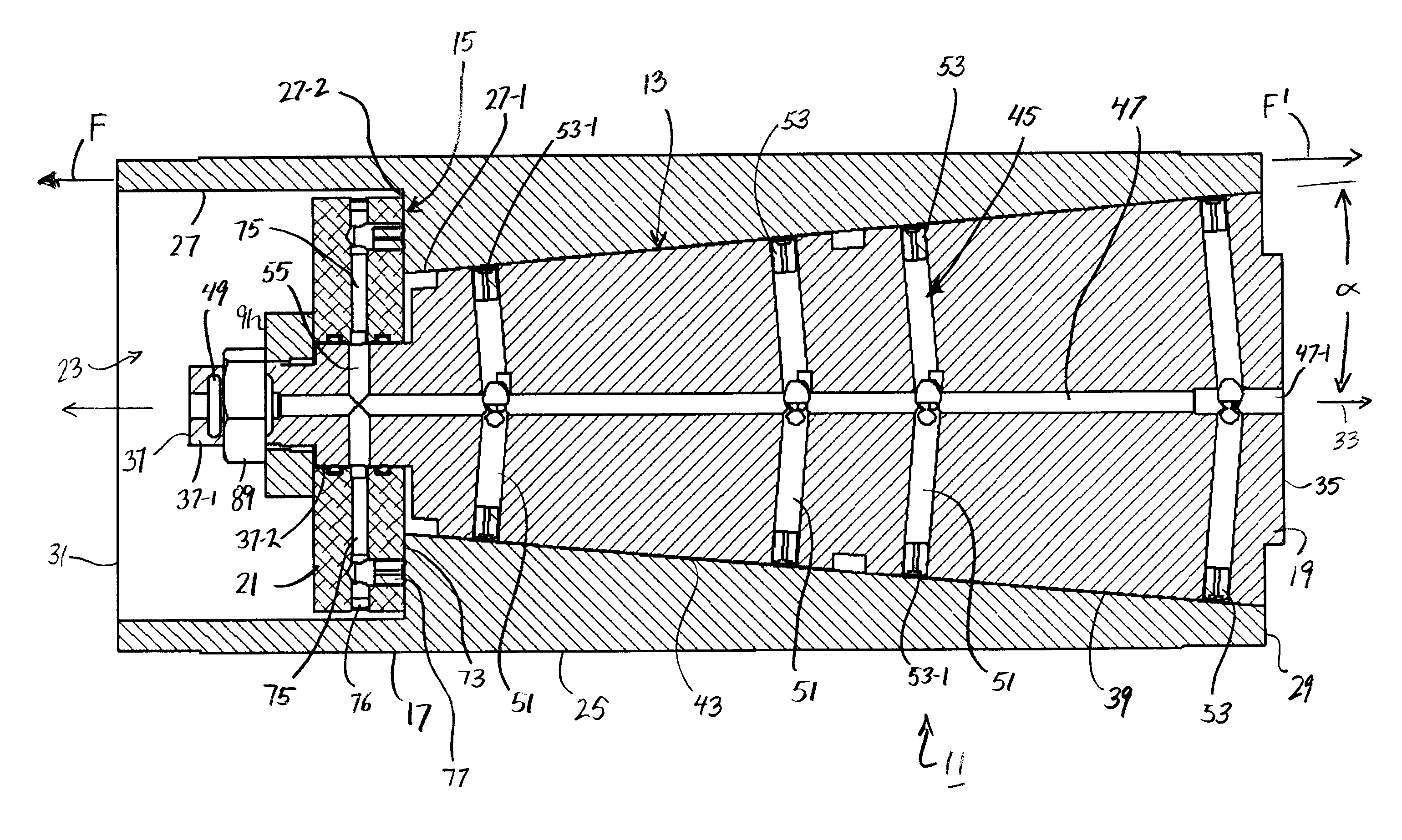
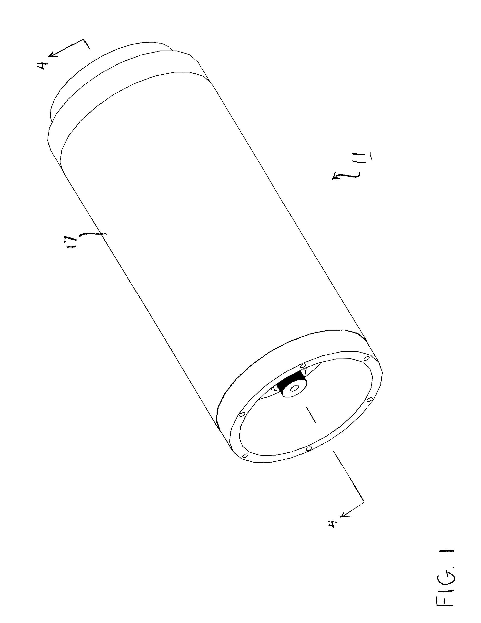
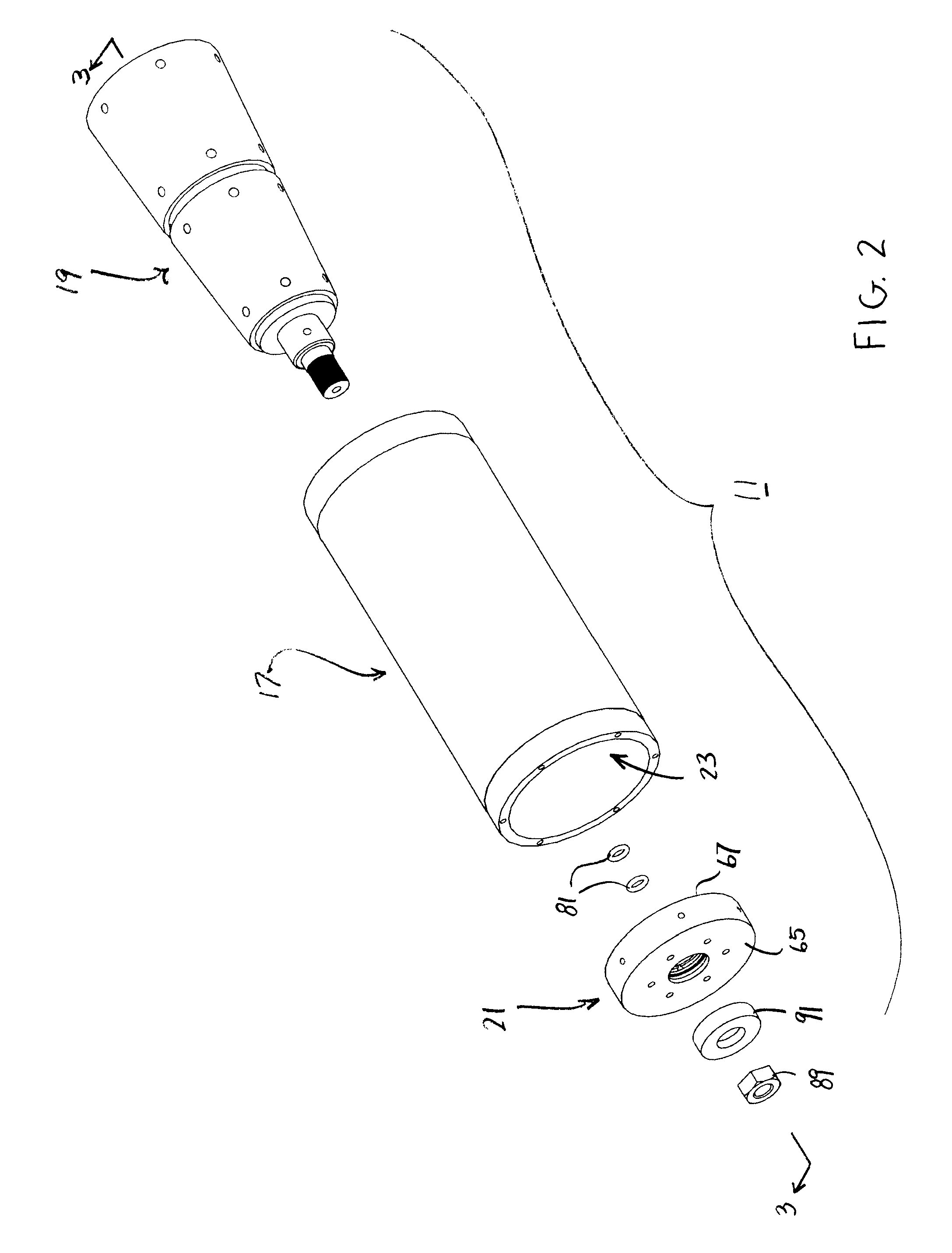
[0042]Referring now to FIGS. 1-4, there is shown a fluid bearing assembly that is constructed according to the teachings of the present invention, the fluid bearing assembly being identified generally by reference numeral 11. In use, fluid bearing assembly 11 can be integrated into, inter alia, a high performance roller designed to transport, redirect or otherwise handle a continuous web of material.

[0043]As will be described further in detail below, fluid bearing assembly 11 comprises a tapered fluid bearing, or tapered bearing, 13 adapted to support radial and axial loads as well as a fluid thrust bearing, or thrust bearing, 15 adapted to support axial loads. In this manner, critical performance characteristics for tapered bearing 13 can be easily controlled through regulation of thrust bearing 15 and, as such, serves as a principal novel feature of the present invention.

[0044]As can be seen, fluid bearing assembly 11 comprises an outer component 17, an inner component 19 extendin...

second embodiment

[0085]Accordingly, referring now to FIGS. 8-10, there is shown a fluid bearing assembly that is constructed according to the teachings of the present invention, the fluid bearing assembly being identified generally by reference numeral 111. Fluid bearing assembly 111 is similar to fluid bearing assembly 11 in that fluid bearing assembly 111 comprises a tapered bearing 113 adapted to support radial and axial loads and a thrust bearing 115 adapted to support axial loads. In this manner, thrust bearing 115 can be used to counterbalance, or oppose, the net axial force created from fluid bearing assembly 111 that would ordinarily result in the separation of components.

[0086]Fluid bearing assembly 111 is also similar to fluid bearing assembly 11 in that fluid bearing assembly 111 includes a generally cylindrical outer component 117, a generally conical inner component 119 extending coaxially within outer component 117, and an annular thrust plate 121 mounted on inner component 119 and ext...


PUM


Abstract

A fluid bearing assembly well-suited for use as high performance, web handling roller includes a stationary inner component that extends coaxially within a rotatable outer component. The inner component includes a single conical member from which extends a narrow stem. The delivery of fluid into a nominal gap between the inner and outer components creates a tapered bearing, with the outer component capable of frictionless rotation relative to the inner component. A thrust plate is axially mounted onto the stem and is retained thereon by a threaded nut. By delivering fluid into a nominal gap between the thrust plate and the outer component, a thrust bearing is created which counterbalances the net axial force produced from the tapered bearing. Furthermore, precise adjustment of the tapered bearing air gap can be achieved through rotation of the threaded nut, thereby enabling certain performance characteristics of the fluid bearing assembly to be modified.

Description

CROSS-REFERENCE TO RELATED APPLICATIONS[0001]The present application claims the benefit of U.S. Provisional Patent Application Ser. No. 61 / 517,338, which was filed on Apr. 18, 2011 in the names of John S. Berg and Dimitar Bentchev, the disclosure of which is incorporated herein by reference.FIELD OF THE INVENTION[0002]The present invention relates generally to machine bearings and, more particularly, to fluid film bearings that are particularly well-suited for use in low inertia, low friction rollers adapted to handle relatively high speed and fragile running webs.BACKGROUND OF THE INVENTION[0003]In many manufacturing applications, a continuous web is utilized as a substrate on which is deposited at least one layer, the web being commonly constructed out of a thin, flexible material, such as paper, plastic, foil, glass or a composite thereof. For example, one or more layers of film are commonly deposited, etched, embossed and / or printed onto a common web of thin, flexible material t...

Claims


Application Information

Patent Timeline
Patent Type & Authority Patents(United States)
IPC IPC(8): F16C32/06F16C33/10F16C17/00
CPCF16C13/026D21G1/0226F16C32/06
Inventor BENTCHEV, DIMITAR B.BERG, JOHN S.
Owner CARPE DIEM TECH
Why Eureka
Try Eureka