Traveling environment recognition device

a technology of environment recognition and recognition device, which is applied in the direction of process and machine control, using reradiation, instruments, etc., can solve the problems of large deviation from the actual spatial position, data cannot be expected to lead to fully accurate vehicle traveling control, etc., to enhance the accuracy of the occupancy grid map, accurate occupancy probability, and accurate recognition

Active Publication Date: 2014-06-03
DENSO CORP
View PDF21 Cites 29 Cited by
  • Summary
  • Abstract
  • Description
  • Claims
  • Application Information

AI Technical Summary

Benefits of technology

[0012]This allows the traveling environment (more specifically, existence of an obstacle to traveling of the own vehicle) of the own vehicle to be expressed by the occupancy probability in the absolute coordinate system, which probability can be updated according to the Bayesian inference, thereby enhancing accuracy of the occupancy grid map. Particularly, in the traveling environment recognition device, the occupancy probability calculated on the basis of information from the radar device, the occupancy probability calculated on the basis of information from the communication device, and the occupancy probability calculated on the basis of information from the storage device that stores map data are blended together to provide a blended occupancy probability of the obstacles to traveling of the own vehicle. This leads to a more accurate occupancy probability than the occupancy probability obtained from the information from one of the radar device, the communication device and the storage device, which allows the traveling environment of the own vehicle to be more accurately recognized.

Problems solved by technology

However, since the traveling environment that can be determined through the map data is less accurate than the actual traveling environment that can be detected in real time through the camera or the radar device, the map data cannot be expected to lead to fully accurate vehicle traveling control.
However, as described above, since the map data is less accurate than the detection result obtained by the camera or the like, combination of the detection result with the map data (more specifically, the link plane associated with the link) as described in Japanese Patent Application Publication No. 2008-3253 may lead to a large deviation from an actual spatial position.

Method used


Image

  • Traveling environment recognition device
  • Traveling environment recognition device
  • Traveling environment recognition device

Examples


Embodiment Construction

[0027]The present invention will be described more fully hereinafter with reference to the accompanying drawings. Like numbers refer to like elements throughout.

[0028](1. System Configuration)

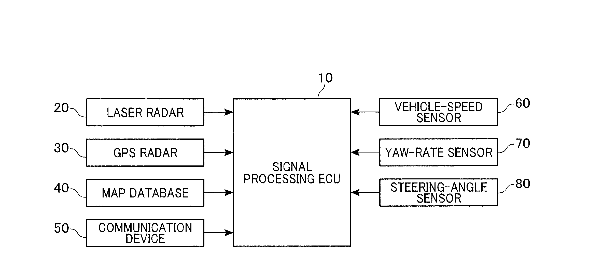
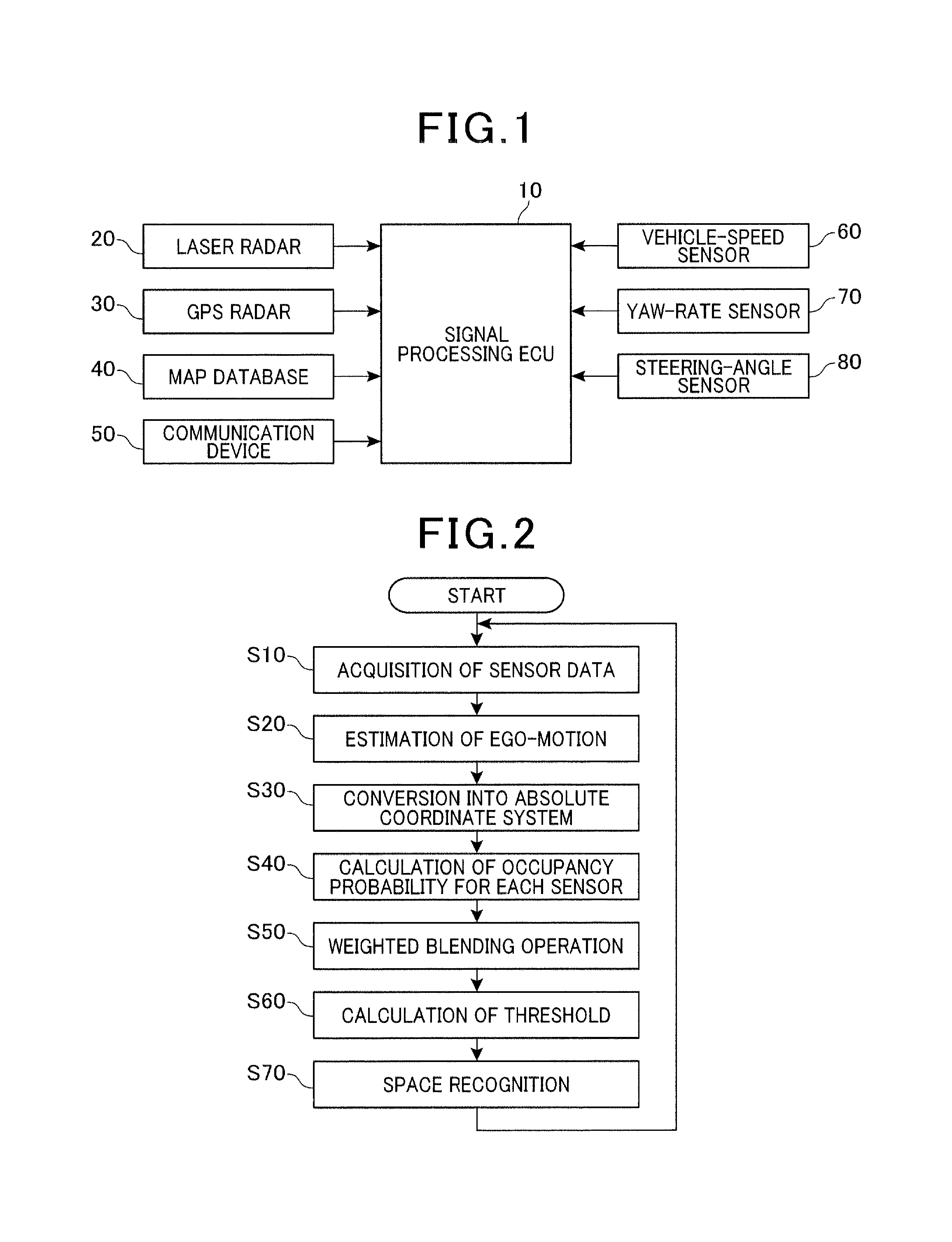
[0029]FIG. 1 shows a block diagram of a traveling environment recognition system in accordance with one embodiment of the present invention. The traveling environment recognition system includes a signal processing electric control unit (ECU) 10, a laser radar 20, a GPS receiver 30, a map database 40, a communication device 50, a vehicle-speed sensor 60, a yaw-rate sensor 70, and a steering-angle sensor 80.

[0030]The signal processing ECU 10 includes a CPU (not shown), a ROM (not shown) and a RAM (not shown), and performs various processes required for the traveling environment recognition of the present embodiment by executing corresponding programs stored, for example, in the ROM.

[0031]The laser radar 20 emits pulsed laser light for 2D scanning from a light emitting section (or a light emittin...


PUM


Abstract

A traveling environment recognition device capable of accurately recognizing a traveling environment of a vehicle. An occupancy grid map that stores an occupancy probability of each obstacle to traveling of the own vehicle for each cell of the occupancy grid map is generated, and the occupancy probability for each cell is updated according to Bayesian inference. More specifically, for each cell of the occupancy grid map, the occupancy probability calculated from information from a radar device, the occupancy probability calculated from information from a communication device, and the occupancy probability calculated from information from a storage device that stores map data are blended to provide an occupancy probability of the obstacles to traveling of the own vehicle, which leads to more accurate traveling environment recognition.

Description

CROSS-REFERENCE TO RELATED APPLICATION[0001]This application is based on and claims the benefit of priority from earlier Japanese Patent Application No. 2010-192456 filed Aug. 30, 2010, the description of which is incorporated herein by reference.BACKGROUND[0002]1. Technical Field[0003]This invention relates to a traveling environment recognition device that recognizes a traveling environment of a vehicle.[0004]2. Related Art[0005]Conventionally, various traveling control techniques based on a traveling environment of the vehicle (such as a forward situation of the vehicle), such as Adaptive Cruise Control (ACC) and Pre-Crash Safety (PCS), have been put into practical use. The ACC is adapted to keep an inter-vehicle distance preset by an occupant of one's own vehicle between the own vehicle and a preceding vehicle in front of the own vehicle. The Pre-Crash Safety (PCS) is adapted to increase braking force of one's own vehicle in cases where a probability of collision of the own vehi...

Claims


Application Information

Patent Timeline
Patent Type & Authority Patents(United States)
IPC IPC(8): G06F17/10
CPCB60W2550/143B60W2520/06B60W2550/408B60W2550/10B60W40/06B60W40/04B60W2550/402B60W2552/20B60W2554/00B60W2556/50B60W2556/65G01S7/4808G01S13/89G01S13/931G01S17/89G01S17/931G01S2013/9323G01S2013/9324
Inventor TAKAGI, KIYOKAZU
Owner DENSO CORP
Why Eureka
Try Eureka