Low vibration cryocooled system for low temperature microscopy and spectroscopy applications

a cryocooler and low-vibration technology, applied in the field of cryogenic research, can solve the problems of many problems associated with low-temperature microscopy, no solution provides a reliable system that supports a sample without vibration and maintains the sample temperature, and achieves the effect of reducing thermal fluctuations of the cryocooler, easy connection and disconnection, and easy disconnection

Active Publication Date: 2014-06-10
MONTANA INSTR
View PDF15 Cites 89 Cited by
  • Summary
  • Abstract
  • Description
  • Claims
  • Application Information

AI Technical Summary

Benefits of technology

[0008]A purpose of the invention is to provide vibration isolated sample mounting for microscopy and spectroscopy of a cryocooled sample. One advantage of preferred embodiments of the invention is that they provide a low vibration, low temperature fluctuating cryocooled sample environment that allows optical access from the top, sides and bottom for microscopy and spectroscopy applications. Another advantage of preferred embodiments of the invention is the achievement of isolation from cryocooler vibrations to the sample and the optics bench, as well as maintaining virtually the same low temperature and heat removal capacity (at the isolated cryocooled sample) of the cryocooler. Another advantage of preferred embodiments of the invention is that it separates the cryocooler assembly and the sample housing assembly into two distinct units that may be easily connected and disconnected. The advantage of this modular architecture is that one cryocooled system can easily connect with a variety of modular application-specific sample areas, each with the same high level of automation, computer control, and mechanical and electronic integration into the whole cryocooled system. Another advantage of preferred embodiments of the invention is that the user may sweep the sample temperature from less than 4 Kelvin (K) to over 300K without turning off the cryocooler. Another advantage of preferred embodiments of the invention is that thermal fluctuations of the cryocooler are significantly reduced with very little rise in the temperature of the sample.

Problems solved by technology

Problems associated with low temperature microscopy are many.
The cooling systems cause sample vibration, maintaining a constant temperature of the sample is likewise a challenge.
There have been attempts to address these problems (see, for example, U.S. Pat. Nos. 3,894,403; 4,161,747; 4,854,131; 4,869,068; 5,327,733; and 5,749,243) yet no solution provides a reliable system that supports a sample without vibration and maintains sample temperature.

Method used


Image

  • Low vibration cryocooled system for low temperature microscopy and spectroscopy applications
  • Low vibration cryocooled system for low temperature microscopy and spectroscopy applications
  • Low vibration cryocooled system for low temperature microscopy and spectroscopy applications

Examples


Embodiment Construction

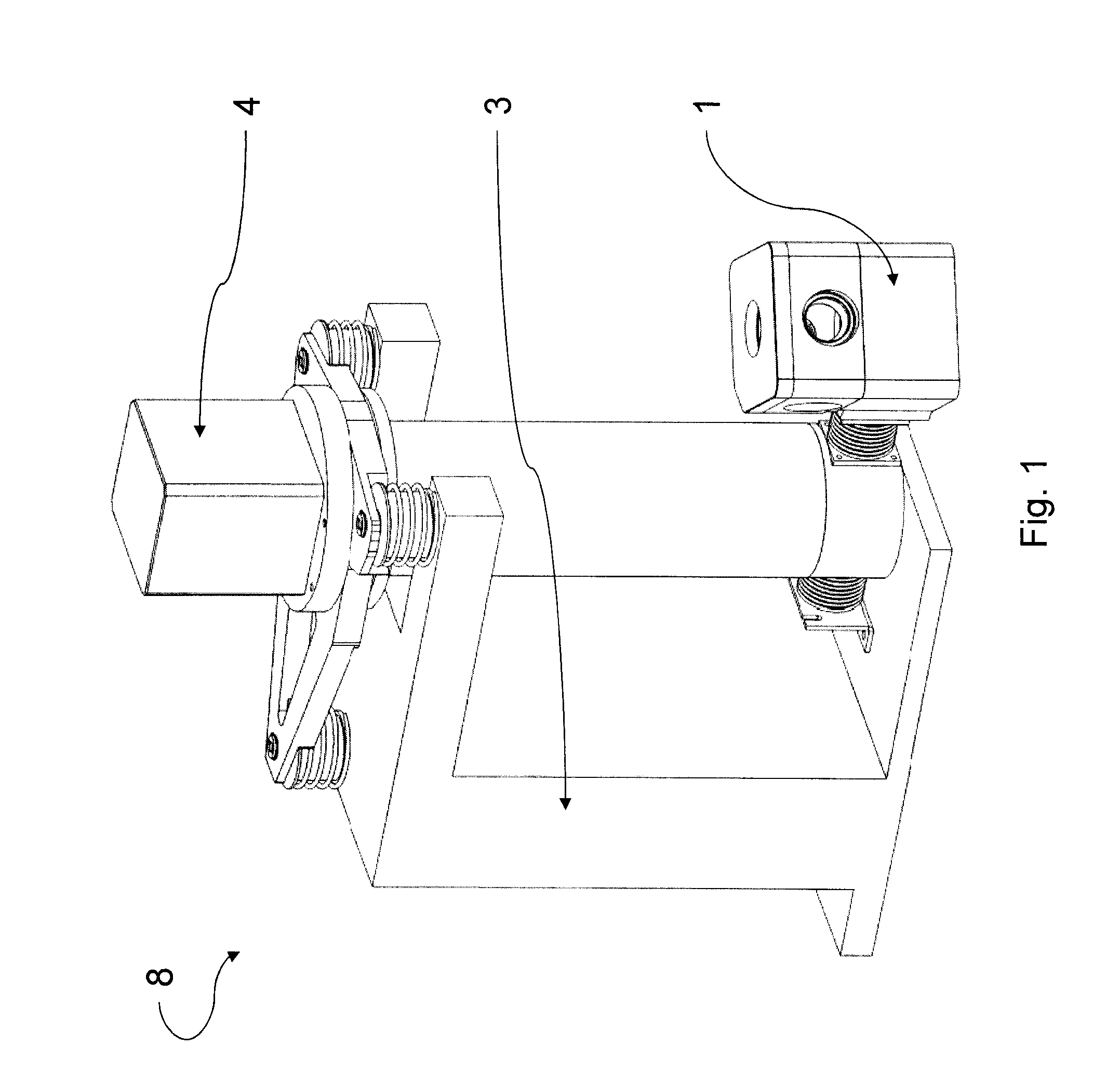
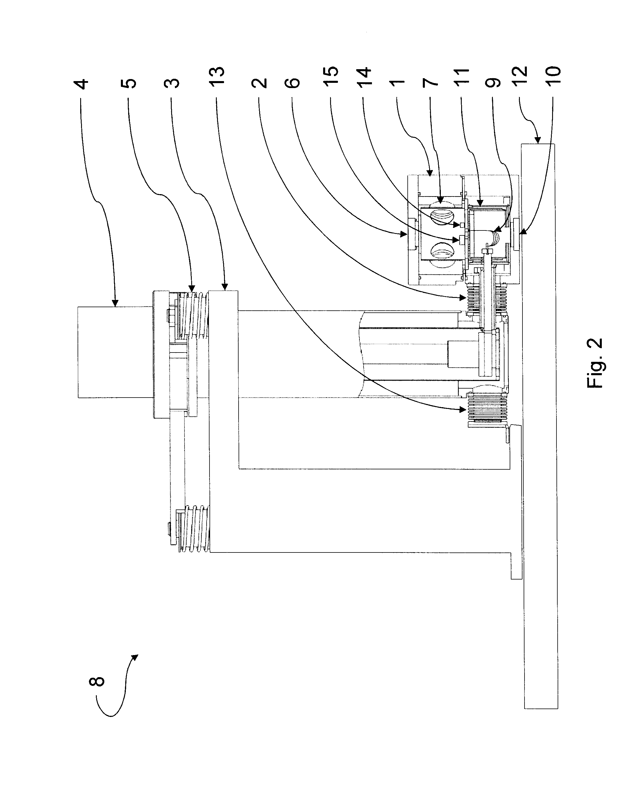
[0052]Referring now to a preferred embodiment of the invention in more detail, in FIGS. 1-3 there is shown a low vibration cryocooled system for low temperature microscopy and spectroscopy 8 having a rigid support 3 which supports a closed-cycle cryocooler expander unit 4, by several spring dampers 5. In a more preferred embodiment, cryocooler expander unit 4 is a Sumitomo Heavy Industries RDK-101D cryocooler. The cryocooler expander unit 4 is preferably connected to separately aligned sample housing 1 and cryogenic sample support 11 by a small diameter flexible hermetic sealing bellows 2 and highly conductive flexible thermal links 9. The diameter of flexible hermetic sealing bellows 2 is preferably in the range from about 0.75 inches to about 3 inches and is more preferably in the range from about 1 inches to about 1.25 inches.

[0053]In normal use, both the rigid support 3 and the sample housing 1 rest on an optical bench 12 or on another rigid plane. In a more preferred embodiment...


PUM

PropertyMeasurementUnit
temperatureaaaaaaaaaa
diameteraaaaaaaaaa

Abstract

A vertical support rigidly mounted to a planar base positions and supports a cryocooler expander unit off axis and away from a sample to be examined. The sample support is likewise rigidly mounted to the planar base with a rigidly mounted sample housing therein. The cryocooler expander unit is suspended in the vertical support by spring dampening bearings. A pair of opposing flexible vacuum bellows connects the cryocooler expander unit to the sample housing and vertical support. This configuration isolates the sample from vibration. Flexible thermal links associated with an predictive electronic closed loop control sequence maintains sample temperature.

Description

CROSS-REFERENCE TO RELATED APPLICATIONS[0001]This application claims the benefits of U.S. Provisional Application No. 61 / 164,448 filed Mar. 29, 2009, the disclosure of which is hereby incorporated by reference in its entirety including all figures, tables and drawings.STATEMENT REGARDING FEDERALLY SPONSORED RESEARCH OR DEVELOPMENT[0002]Not applicable.REFERENCE TO SEQUENCE LISTING, A TABLE, OR COMPUTER PROGRAM LISTING COMPACT DISC APPENDIX[0003]Not ApplicableBACKGROUND OF THE INVENTION[0004]The present invention relates to systems and methods for cryogenic research. More particularly, the present invention relates to systems and methods for microscopy and spectroscopy of cryocooled samples.[0005]Problems associated with low temperature microscopy are many. The cooling systems cause sample vibration, maintaining a constant temperature of the sample is likewise a challenge. There have been attempts to address these problems (see, for example, U.S. Pat. Nos. 3,894,403; 4,161,747; 4,854,...

Claims


Application Information

Patent Timeline
Patent Type & Authority Patents(United States)
IPC IPC(8): F25J3/00G01N21/01G05D23/00G01C1/10F25B9/00F25B19/00F25B1/10
CPCF25B9/00F25J3/00G01N21/01F25B19/00G01C1/10F25B1/10G05D23/00F28F21/085F25D23/00F25B9/002G02B21/28Y10T29/49826C22F1/08B23K9/16B23P15/26
Inventor MAURITSEN, LUKE R.SIMMONDS, MICHAEL B.GRIFFING, DAN
Owner MONTANA INSTR
Why Eureka
Try Eureka