Image forming apparatus and image forming method

a technology of image forming and forming apparatus, which is applied in the direction of recording apparatus, mechanical recording, instruments, etc., can solve the problems of reducing the reliability of printing, reducing the quality of printed images, and causing bleeding of ink (bleeding of ink) more likely to occur

Inactive Publication Date: 2014-06-10
RICOH KK
View PDF26 Cites 41 Cited by
  • Summary
  • Abstract
  • Description
  • Claims
  • Application Information

AI Technical Summary

Problems solved by technology

As a result, a flying direction of the ink may deviate from a desired flying direction and / or the nozzle may be clogged due to the paper powder or dust; thereby degrading a quality of printed image and reducing the reliability of printing.
However, when such a low-viscosity ink is used, bleeding of ink (ink bleeding) is more likely to occur when the ink is deposited on the surface of the recording paper.
However, in this method, it is always required to apply a treatment liquid to aggregate the pigment in the ink, which becomes necessary to add a device for applying the treatment liquid and may reduce a printing speed.

Method used


Image

  • Image forming apparatus and image forming method
  • Image forming apparatus and image forming method
  • Image forming apparatus and image forming method

Examples


embodiments

Preparation of Black Conductive Ink

[0066]First, 35.0 wt % of sulfonic group binding-type carbon black pigment dispersion, CAB-O-JET-200 (Cabot Specialty Chemicals, Inc.) (solid content: 20 wt %), 10.0 wt % of 2-pyrrolidone, 14.0 wt % of glycerin, 0.9 wt % of propylene glycol monobutyl ether, 0.1 wt % of dehydroacetic soda, and water as a balance were mixed to obtain a mixture. Next, the pH of the mixture was adjusted to 9.1 by adding an aqueous solution of 5 wt % lithium hydroxide and then the mixture was subjected to pressure filtration using a membrane filter having an average pore size of 0.8 thereby obtaining black conductive ink.

Preparation of Yellow Conductive Ink

[0067]First, 40.0 wt % of sulfonic group binding-type yellow pigment dispersion, CAB-O-JET-270Y (Cabot Specialty Chemicals, Inc.) (solid content: 10 wt %), 15.0 wt % of triethylene glycol, 25.0 wt % of glycerin, 6.0 wt % of propylene glycol monobutyl ether, 0.1 wt % of dehydroacetic soda, and water as a balance were m...

first embodiment

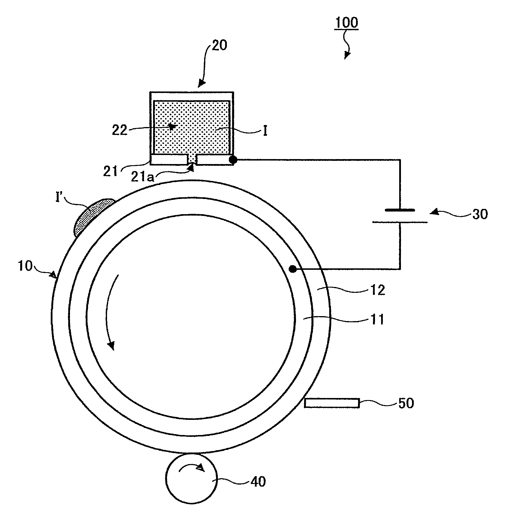
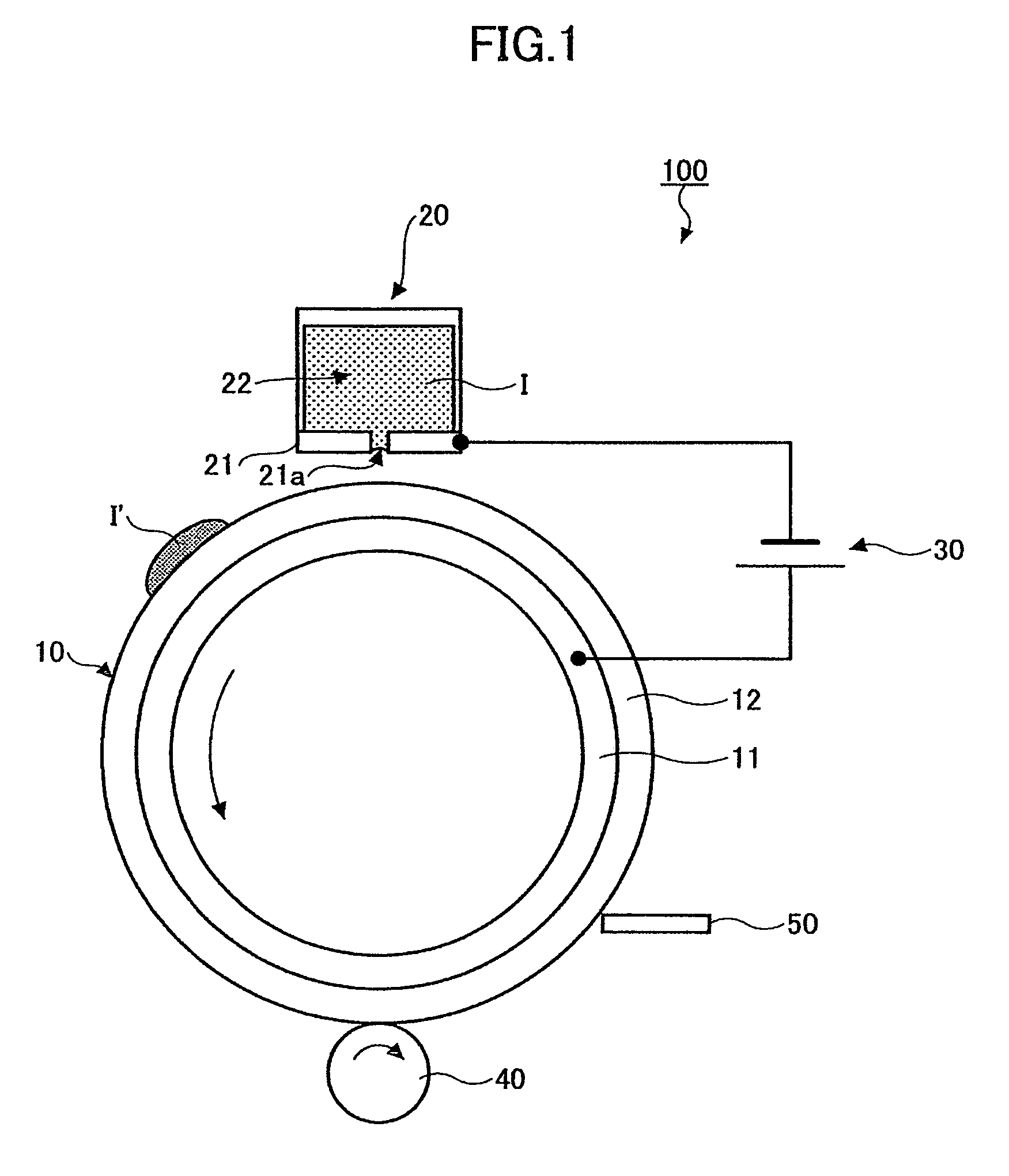
[0070]According to a first embodiment of the present invention, an image forming apparatus as shown in FIG. 6 is provided. The image forming apparatus in FIG. 6 is the same as the image forming apparatus in FIG. 1 except that the image forming apparatus in FIG. 6 includes a yellow recording head 20Y and a black recording head 20K in this order for printing their color images in this order. The same reference numerals are used in FIG. 6 to describe the same or equivalent components of FIG. 1 and the descriptions thereof may be omitted. The intermediate transfer drum 10 includes an aluminum round tube (i.e., conductive substrate 11) and a silicone rubber layer (i.e., conductive layer 12) formed on the outer circumference of the aluminum round tube, the silicone rubber layer having volume resistivity of 5 Ω·cm and thickness of 0.2 mm and including dispersed carbon. The intermediate transfer drum 10 is driven by a drive means (not shown) so as to be rotated at a line speed of the outer ...

second embodiment

[0082]According to a second embodiment of the present invention, the evaluation is performed in the same conditions as that in the first embodiment of the present invention except that, instead of using the intermediate transfer drum 10, a stainless round tube (i.e., conductive substrate 11) is used as the intermediate transfer drum.

[0083]As a result of the evaluation, FIG. 10 shows a relationship between pH values and voltages of the power source and FIG. 11 shows a relationship between the roundness rate with respect to the area K where black pigment is included and the voltage of the power source. In FIGS. 10 and 11, data of FIGS. 8 and 9, respectively, are also plotted using dotted lines for comparison. From FIG. 10, the pH values start decreasing at a slightly higher voltage when compared with data of FIG. 8 (i.e., data of the first embodiment of the present invention). On the other hand, from FIG. 11, the effect of controlling the bleeding of black ink to the dot of other colo...


PUM

PropertyMeasurementUnit
volume resistivityaaaaaaaaaa
pore sizeaaaaaaaaaa
thicknessaaaaaaaaaa

Abstract

A disclosed image forming apparatus includes a recording head having a nozzle capable of ejecting inductive ink including water, a first intermediate transfer body having a conductive surface on which an ink image is to be formed by temporarily forming a liquid-column bridge between the conductive surface and the nozzle, the liquid-column bridge being made of the inductive ink, a voltage application unit applying a voltage between the inductive ink and the conductive surface so that water included in the liquid-column bridge is electrolyzed, and a transfer unit transferring an ink image formed on the first intermediate transfer body to a recording medium.

Description

TECHNICAL FIELD[0001]The present invention relates to an image forming apparatus and an image forming method.BACKGROUND ART[0002]As inkjet recording methods, they are known methods including an actuator driven method represented by a piezoelectric inkjet recording method and a heating and film boiling method represented by a thermal inkjet recording method. In any method, in accordance with image data to be printed, ink is ejected from a nozzle of a recording head so that the image data are formed. When compared with the electrophotographic recording method, the inkjet recording method can be implemented easier; therefore, the inkjet recording method is applied in various image forming apparatuses such as a printer, a facsimile machine, a copier and the like.[0003]As a main part of an imaging engine, such an image forming apparatus includes a recording head having a nozzle from which ink is ejected. If a process that the ink ejected from the nozzle of the recording head is printed o...

Claims


Application Information

Patent Timeline
Patent Type & Authority Patents(United States)
IPC IPC(8): B41J2/01
CPCB41J2/0057B41M5/0256B41M5/00B41J2/385
Inventor TSUKAMOTO, TAKEOUSUI, YUUMASEO, MANABUHASEGAWA, AINOORITO, TAKESHISUZUKI, RYOTA
Owner RICOH KK
Why Eureka
Try Eureka