
Removable handle scan body for impression trays and radiographic templates for integrated optical and CT scanning

a scanner body and integrated technology, applied in the field of dental implants and orthodontic treatment planning, can solve the problems of insufficient detail and accuracy required for the production of surgical drill templates, orthodontic aligners, impression caps,

Inactive Publication Date: 2014-06-10
GREENBERG SURGICAL TECH
View PDF5 Cites 11 Cited by
  • Summary
  • Abstract
  • Description
  • Claims
  • Application Information

AI Technical Summary

Benefits of technology

This patent is about a new method for combining modern technology and a removable shape to improve the registration of data from a CT scan and an optical scan. The method also avoids relying on surfaces of adjacent teeth to determine a dental implant trajectory. Instead, the dental form and underlying bony anatomy are used to determine the desired dental implant trajectory. The technical effects of this new method are improved accuracy and efficiency in dental implant treatment planning.

Problems solved by technology

However, these conventional methods have limitations in that they require the bonding of a shape of known dimensions (SKD) on the dentition itself as in the methods of U.S. Pat. No. 6,319,006 and U.S. Publication No. 2011 / 0008751 so that the dentition can be acquired by the CT and optical scans for registration.
Conventional methods are thus limited by the need to apply physical markers of standardized known dimensions and shape to the teeth themselves.
Moreover, these conventional methods do not provide for the creation or use of custom impression trays or standardized impression trays with modular or removable parts, let alone for impression trays or radiographic templates having removable shapes of known dimensions.
The merger of two data sets of digitized CT images involving the superimposition of a separate CT image of the radiographic template to CT bone images of the radiographic template in the patient's mouth also does not provide a sufficient level of detail and accuracy required for the production of some types of dental models, surgical drill templates and orthodontic aligners.
Furthermore, another limitation of conventional imaging methods is their dependence on surfaces of adjacent teeth for determining a dental implant trajectory.

Method used


Image

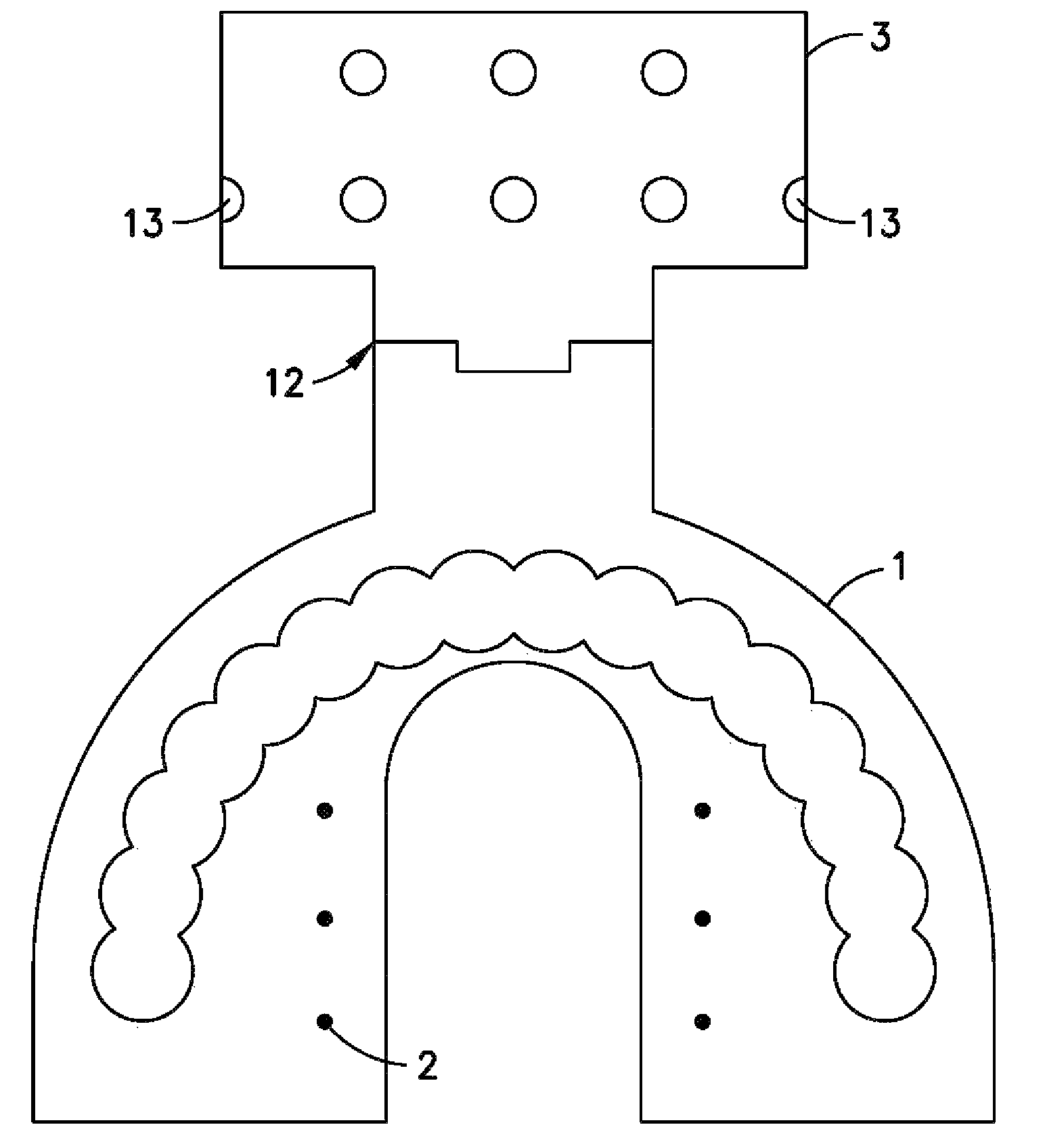
  • Removable handle scan body for impression trays and radiographic templates for integrated optical and CT scanning
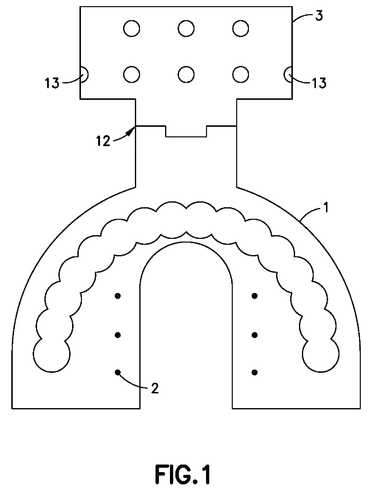
  • Removable handle scan body for impression trays and radiographic templates for integrated optical and CT scanning
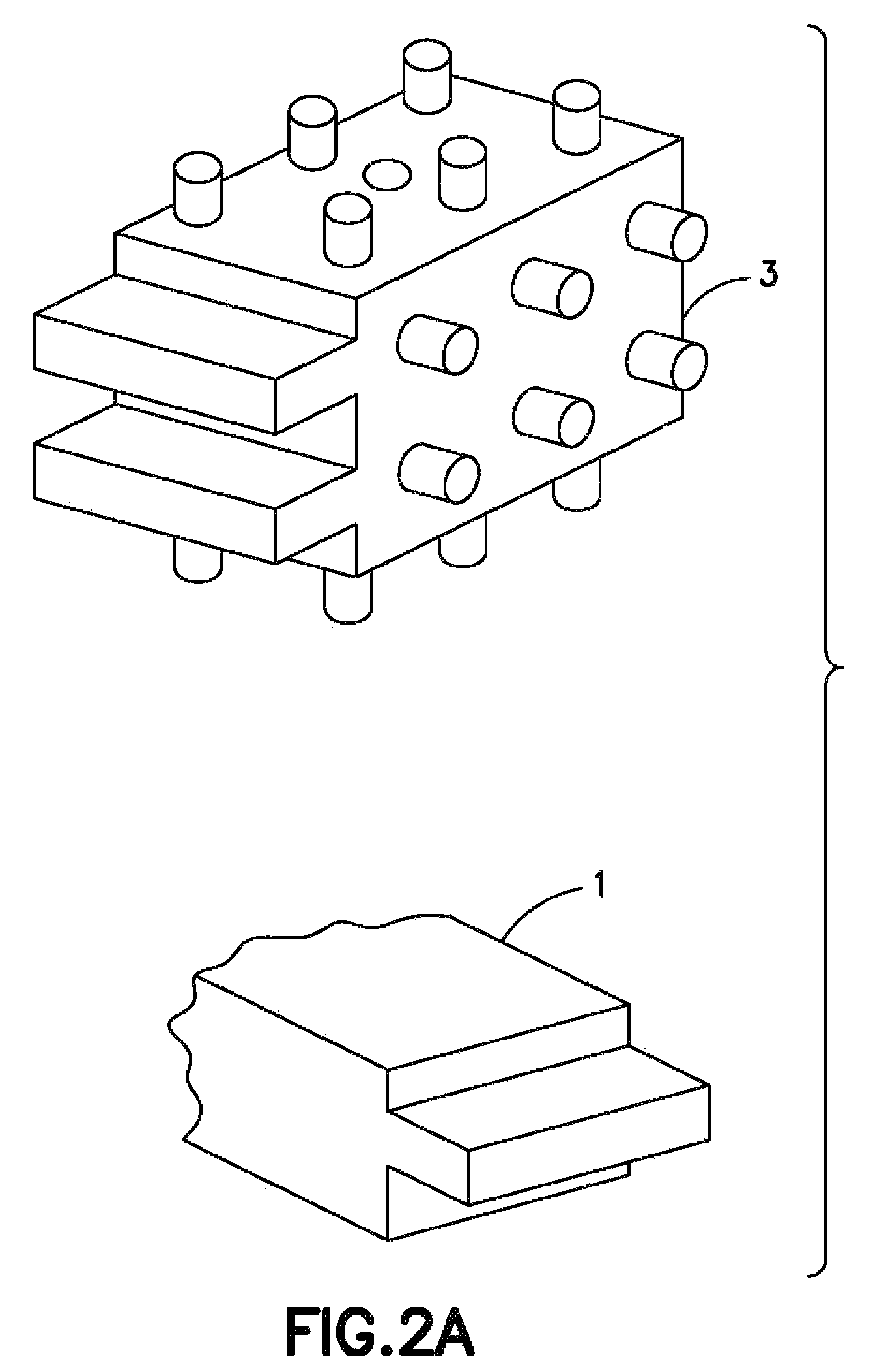
  • Removable handle scan body for impression trays and radiographic templates for integrated optical and CT scanning

Examples


Embodiment Construction

[0028]Example embodiments of the present invention utilize processes disclosed in R. Jacobs et. al., “Predictability of a three dimensional planning system for oral implant surgery”, Dentomaxillofacial Rad., 1999, 28, pp. 105-111, and Van Steenberghe, “A custom template and definitive prosthesis”, Int. J. Maxillofacial Implants, 2002, 17, pp. 663-670, as well as processes in U.S. Pat. No. 7,574,025, the entire contents of which are incorporated herein by reference. U.S. Pat. No. 7,574,025 discloses the use of a dual scan process of a radiographic scan appliance or template with fiducial markers for performing a scan of a radiographic template in a patient's mouth and a separate scan of the radiographic template in a Styrofoam box, thus creating two data sets that allow for the creation of an artifact corrected image. The two data sets of digitized CT images are merged in planning software with registration and superimposition of the separate image of the radiographic template to the...


PUM


Abstract

A device for use in optical scanning and CT scanning including a radiographic template and at least one shape of known dimension (SKD). The radiographic template includes a plurality of radio-opaque markers and is configured to take an impression of at least one surface of a patient. The SKD is removably attached to the radiographic template and serves as a basis for registration of data of a CT scan of the device with data of an optical scan of the device. The device may further comprise a mounting plate. The SKD is mounted on the mounting plate such that the at least one SKD is in an exact same position with respect to surfaces in a model formed from the impression as when the impression of the patient is formed in the radiographic template.

Description

RELATED APPLICATIONS[0001]This application claims priority from U.S. Provisional Patent Application Ser. No. 61 / 439,168, which was filed on Feb. 3, 2011, the entire contents of which are incorporated herein by reference.1. FIELD OF THE INVENTION[0002]The present invention relates to dental implant and orthodontic treatment planning and in particular to the creation of integrated CT and optical scan data for dental implant and orthodontic treatment planning and the production of dental models, surgical drill templates and orthodontic aligners.2. DESCRIPTION OF THE RELATED ART[0003]CT scanned 3D images and virtual optically acquitted images of dentitions are conventionally registered to allow for treatment planning for the placement of dental implants and orthodontic treatment aligners. For example, U.S. Pat. Nos. 7,573,583 and 7,355,721 describe conventional imaging methods that relate to the well-known dental software E4D Compass. U.S. Pat. No. 6,319,006 relates to another conventio...

Claims


Application Information

Patent Timeline
Patent Type & Authority Patents(United States)
IPC IPC(8): A61C8/00G06K9/00A61B6/51
CPCA61C9/004A61C7/08G09B23/286A61B6/4423G09B23/283G06K9/00597A61B6/5235A61B6/14A61C1/084A61C13/0004B33Y80/00B33Y50/00G06V40/18A61B6/51
Inventor GREENBERG, ALEX, M
Owner GREENBERG SURGICAL TECH
Learn More