Carbon dioxide capture interface and power generation facility

a technology of carbon dioxide and power generation facilities, applied in lighting and heating apparatus, combustion types, separation processes, etc., can solve the problem of not being readily adaptable to pfbc technology, benfield process, etc., and achieve the effect of reducing the co2 greenhouse gas emissions

Active Publication Date: 2014-06-17
POLVI ESKO OLAVI
View PDF10 Cites 5 Cited by
  • Summary
  • Abstract
  • Description
  • Claims
  • Application Information

AI Technical Summary

Benefits of technology

[0008]Typically, in the standard PFBC cycle, a gas turbine uses flue gas from the PFBC boiler to drive the combustion air compressor. For the interface, the standard flue gas driven gas turbine compressor is replaced with a compressor driven by an electrical variable frequency drive (VFD) motor and a flue gas expander. The flue gas is cleaned and used to drive the flue gas expander. The flue gas expander convert the energy in the pressure reduction to additional torque to assist the VFD to drive the combustion air compressor. Compared to a CO2 capture process based on the standard PFBC process with the gas turbine, the use of the HRSG / VFD motor / gas expander combination will give a greater freedom to minimize the amount of energy losses due to the CO2 capture process and thereby improve efficiency. Rather than as in the standard PFBC technology, which uses a standard frame size of a gas turbine driven compressor that limits the available amount of combustion air and to operate efficiently has a gas turbine that requires high gas temperature and flue gas mass flow, a VFD motor in combination with a flue gas expander is used to drive the compressors for supply of the combustion air to the PFBC process. The VFD motor and gas expander combination boosts the overall flexibility of the interface by allowing for greater ranges of compressor capacity and gas temperature. Thus the combustion air supply, gas temperatures, and the PFBC boiler size can be selected more freely.
[0011]In various embodiments, the present invention combines a PFBC boiler and Benfield carbon dioxide capture processes to provide up to 95% reduction of the CO2 greenhouse gas emissions from coal combustion. Further this combination of the Benfield capture process and a PFBC boiler burning a mix of coal and renewable biomass can result in a power plant with a negative carbon foot print.
[0015]In various embodiments, the invention provides a power generation facility having low emissions and being capable of capturing pressured carbon dioxide in combustion gas emitted from a PFBC facility. The facility has carbon dioxide capture ratio above 90%, and is expected to meet all the US EPA emission limits for generation facilities to low emissions of sulfur oxides, nitrogen oxides, volatile organic compounds, carbon monoxide and particulate matter.

Problems solved by technology

However, as with other power generation processes that utilize fossil fuels, PFBC produces carbon dioxide (CO2) emissions.
However, even though the pressure at which the Benfield process operates would be compatible with the PFBC process, some other process conditions, such as the maximum allowable temperature for the CO2 capturing agent and the level of SO2, and NOx, prevent the Benfield process from being readily adaptable for use with PFBC technology.

Method used


Image

  • Carbon dioxide capture interface and power generation facility
  • Carbon dioxide capture interface and power generation facility
  • Carbon dioxide capture interface and power generation facility

Examples


Embodiment Construction

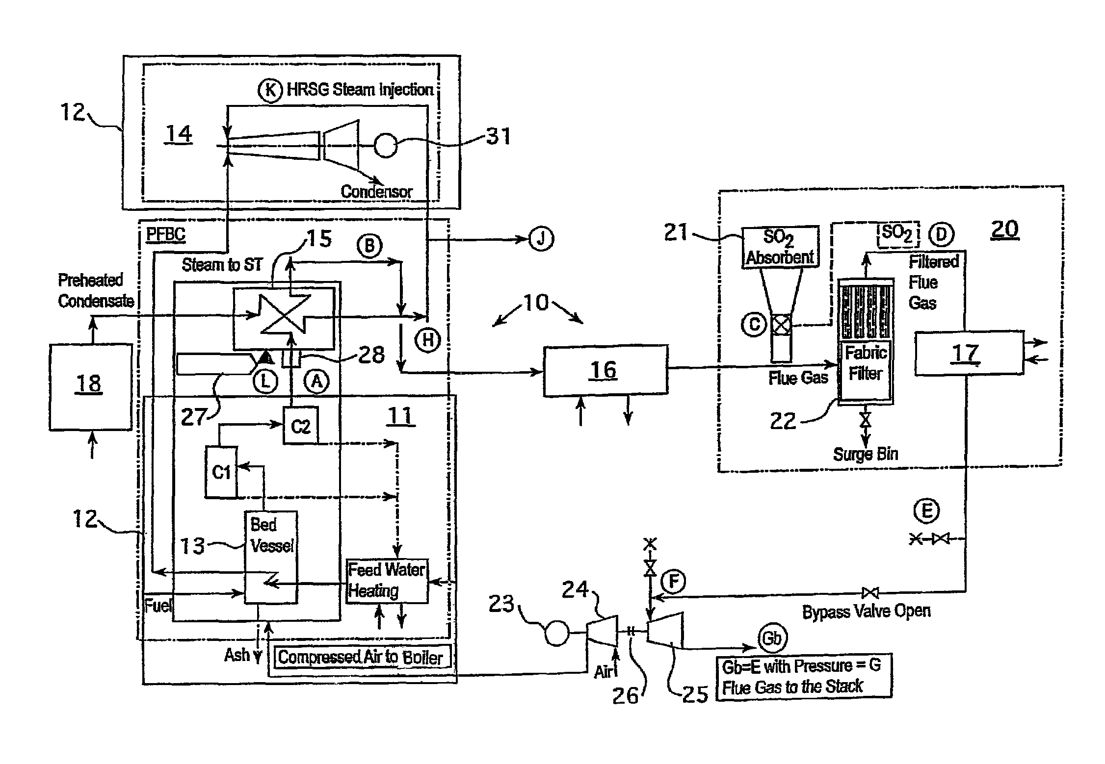
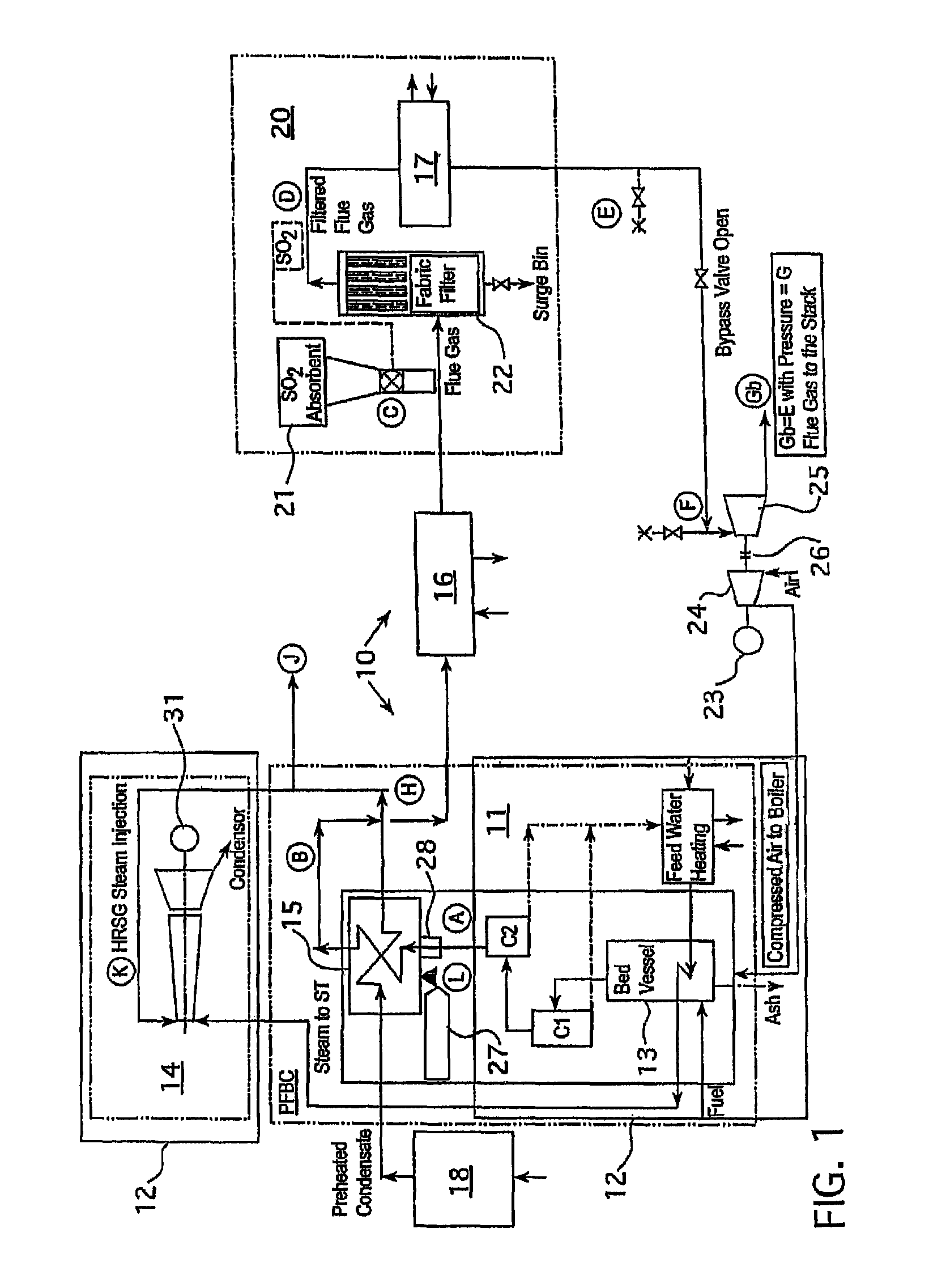
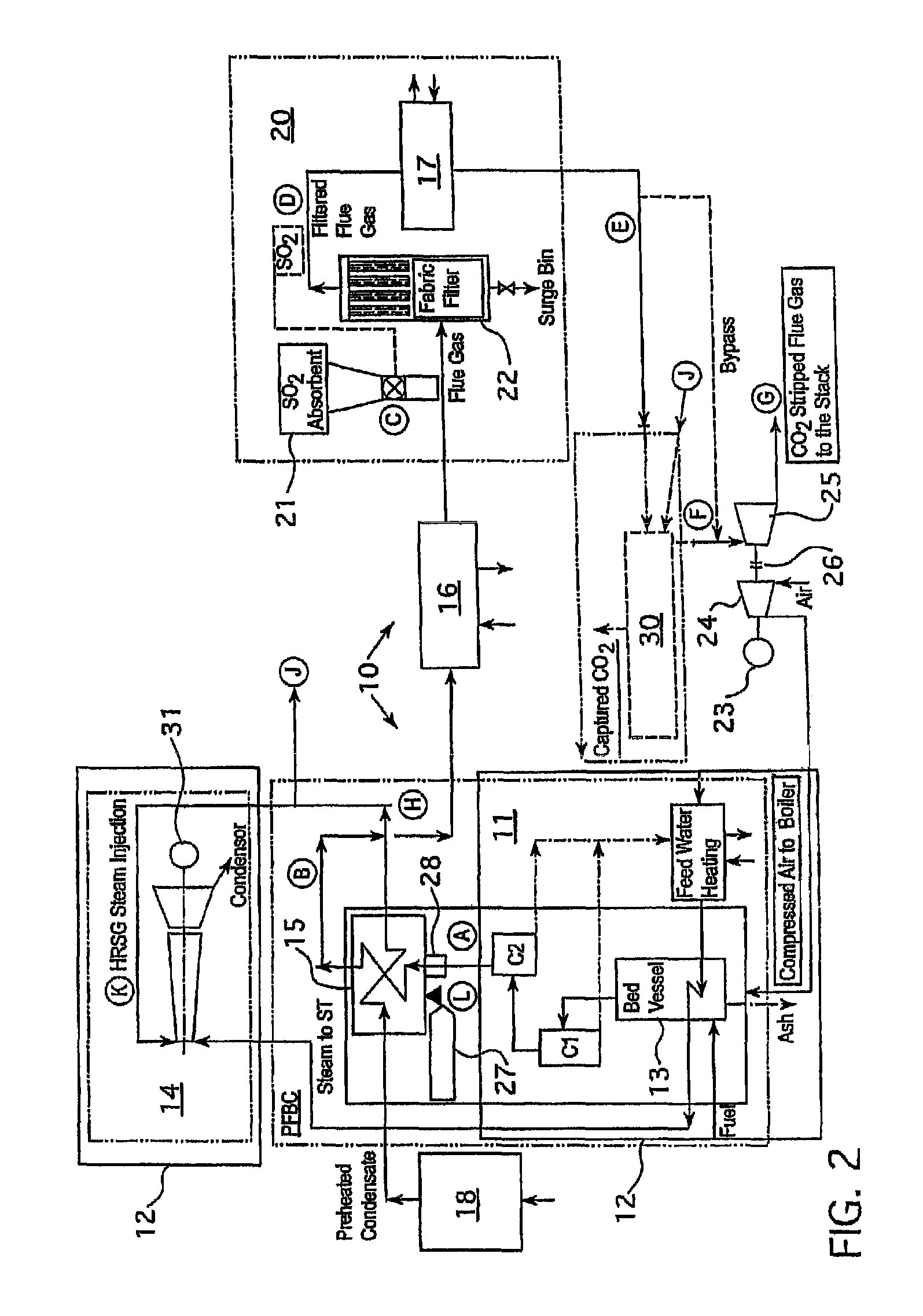
[0022]In embodiments the invention is directed to a readiness interface to enable a PFBC plant to be ready for the addition of a carbon dioxide capture system. The interface comprises configuring an HRSG to cool pressurized flue gas output from the PFBC plant and substituting a VFD motor / gas expander driven compressor for the typical gas turbine compressor to run the PFBC process. The carbon dioxide capture system can be added on later without any impact or changes to the PFBC process, a change which could not be done on the “standard” PFBC with the gas turbine. An advantage of the readiness interface is the plant can be “ready” for the addition of a carbon dioxide capture system, but built without it, which, considering the current uncertainty about the carbon dioxide regulation, can be a benefit from a commercial point of view.

[0023]An overview of the readiness interface is illustrated for example in FIG. 1. Interface 10 includes gas to water pressurized heat recovery steam genera...


PUM

PropertyMeasurementUnit
temperatureaaaaaaaaaa

Abstract

An interface for a pressurized fluidized bed combustion facility is disclosed that enables future addition of carbon dioxide capture technology to capture facility flue gas emissions. The interface includes a gas to water pressurized heat recovery steam generator to cool facility flue gas and provide steam to the facility steam turbine generator. A VFD motor and flue gas expander are coupled to a combustion air compressor to energize the facility. The expander is synchronized over a SSS-clutch to drive the compressor. The interface in combination with carbon capture technology and methods for conditioning flue gas are also disclosed.

Description

BACKGROUND OF THE INVENTION[0001]Various pollution control technologies have been implemented to control emissions from fossil fuel burning facilities, such as fossil fuels which are used for power generation. The pressurized fluidized bed combustion (PFBC) technology is being developed to utilize wet waste coal for highly efficient power generation with minimal emissions of sulfur dioxide, nitrogen oxide, and mercury. However, as with other power generation processes that utilize fossil fuels, PFBC produces carbon dioxide (CO2) emissions. The upcoming CO2 regulation will require new carbonaceous fuel burning power plants to have means for CO2 capture. Thus, the readiness to capture these CO2 emissions will dictate the viability of applying the PFBC technology on a commercial scale to utilize wet waste coal or other carbonaceous fuels for power generation.[0002]Currently, the only presently commercially used technology for carbon capture known to the inventor, that is potentially su...

Claims


Application Information

Patent Timeline
Patent Type & Authority Patents(United States)
IPC IPC(8): F01K23/06F23C10/16F01K23/10
CPCF23C10/16F01K23/062Y02E20/32
Inventor POLVI, ESKO, OLAVI
Owner POLVI ESKO OLAVI
Why Eureka
Try Eureka