
Method of operating a fast scanning mirror

a scanning mirror and mirror technology, applied in the direction of instruments, optical elements, angle measurement, etc., can solve the problems of much lower friction and thereby far faster respons

Active Publication Date: 2014-06-17
ARETE ASSOCIATES INC
View PDF8 Cites 93 Cited by
  • Summary
  • Abstract
  • Description
  • Claims
  • Application Information

AI Technical Summary

Benefits of technology

The patent describes a new device that uses actual bearings instead of torsional flexures, which can result in much faster response times and lower friction levels. We have found various methods to improve this device and have confirmed that it can be made much faster than previous MEMS devices.

Problems solved by technology

In particular, this apparatus—employing actual bearings rather than the torsional flexures of the closest prior art—offers the potential for much lower friction and thereby far faster response.

Method used


Image

  • Method of operating a fast scanning mirror
  • Method of operating a fast scanning mirror
  • Method of operating a fast scanning mirror

Examples


Embodiment Construction

[0131]Preferred embodiments of our invention provide an optically agile imaging system, with related methods, based upon certain active optical components—in combination with a servoed-beam-steering subsystem according to the coowned patent documents listed earlier. The result encompasses a small, lightweight and relatively economical sensor technology.

[0132]This technology is most typically, but not necessarily, for use with small unmanned vehicles—whether aerial or otherwise—as well as manned craft and indeed stationary installations. Preferred embodiments of the invention have several practical applications mentioned earlier.

[0133]The resulting capabilities enable e.g. commercial air traffic systems, astronautical operations and military agencies to enjoy very greatly enhanced but low-cost imaging—including persistent surveillance and pointing. Advanced imaging, using electronically addressable pointing and imaging capability without a conventional gimbal, enclosing the entire op...


PUM


Abstract

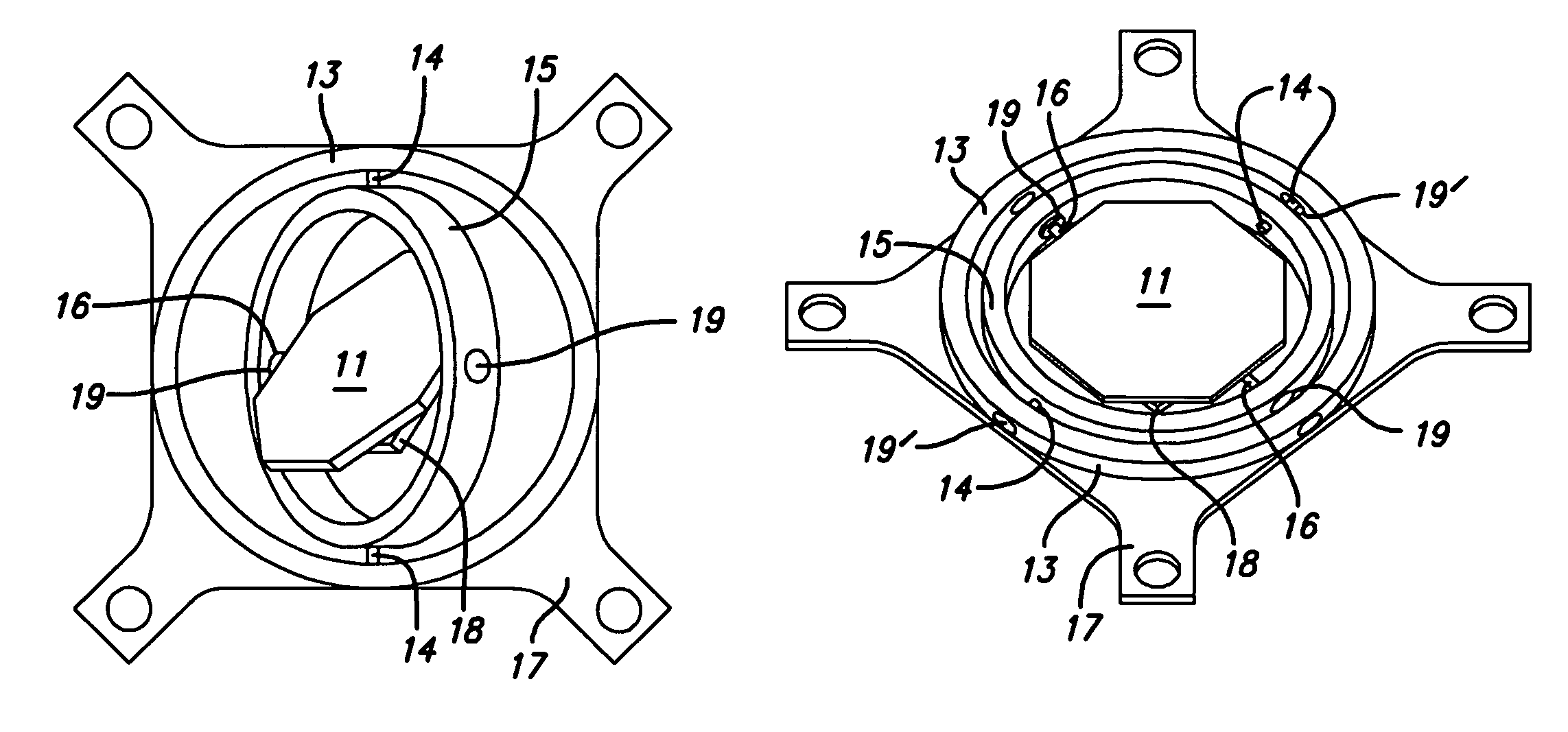
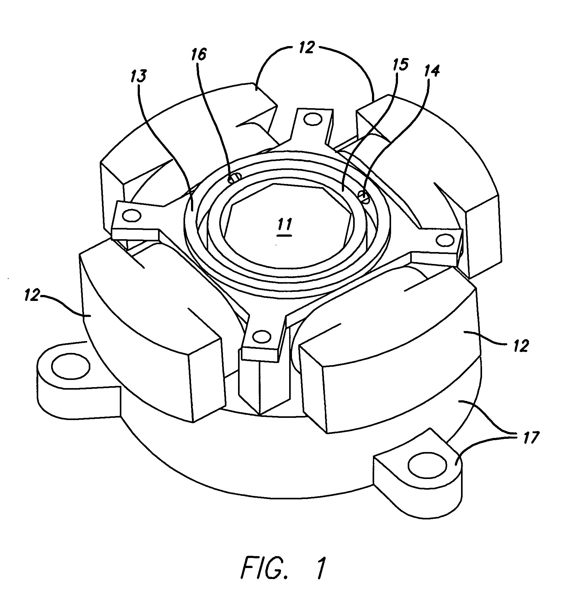
The mirror has a base, inner stage, reflector, controller, and mechanical subsystems pivotally supporting stage and reflector: subsystem #1, the stage (about one rotation axis, relative to the base); subsystem #2, the reflector (about another axis, relative to the stage). Stage and reflector each rotate on respective jewel, ceramic or other refractory bearings. Controller establishes stage / base and reflector / stage angles. Subsystems include respective bearings. The method includes (1) using the two-axis mechanism to receive, and measure an incident angle of, incident rays from an external object; (2) then using that mechanism to direct a radiation beam from a laser source toward the external object, responsive to incident rays. Optionally step (1) operates the mirror at peak acceleration, or minimum response time, as function of mirror thickness; and provides two- to three-millimeter mirror thickness. Optionally step (2) directs the beam to disrupt object function or impair object structure.

Description

RELATION BACK[0001]This document claims priority of copending and coowned U.S. provisional patent applications 60 / 999,159 of Hunt and Hillman et al., entitled “OPTICAL SYSTEM WITH MINIATURE SCANNING MIRROR” and filed Oct. 15, 2007, and 61 / 125,915 of Paul et al., entitled “ELECTROOPTICAL SENSOR TECHNOLOGY . . . ” and filed Apr. 30, 2008.[0002]Other coowned earlier patent documents that are of interest, but of which we do not claim priority for purposes of this document, are U.S. “regular” (nonprovisional) application Ser. No. 11 / 796,603 of Kane, entitled “OPTICAL SYSTEMS AND METHODS USING LARGE MICROELECTROMECHANICAL-SYSTEMS MIRRORS” and filed Apr. 28, 2007; and its then-copending parent application, now U.S. Pat. No. 7,297,934 of Kane, entitled “OPTICAL SYSTEM”, together with their precursor provisional and international applications. All these four patent documents, and further documents incorporated therein, are wholly incorporated by reference into this present document.BACKGROUN...

Claims


Application Information

Patent Timeline
Patent Type & Authority Patents(United States)
IPC IPC(8): G01B11/26G02B7/182
CPCG02B7/1821G02B26/105G01C15/00G02B7/182G02B26/101G01C11/025B33Y80/00
Inventor KANE, DAVID M.HILLMAN, KELLYHORNBERG, CHRISTOPHERHUNT, JOHNPAUL, ANDREW E.
Owner ARETE ASSOCIATES INC
Learn More